
Applied Statics and Strength of Materials (6th Edition)
6th Edition
ISBN: 9780133840544
Author: George F. Limbrunner, Craig D'Allaird, Leonard Spiegel
Publisher: PEARSON
expand_more
expand_more
format_list_bulleted
Videos
Textbook Question
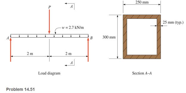
Chapter 14, Problem 14.51SP
A rectangular hollow shape carries loads as shown. Calculate the maximum value of P if the allowable stresses are
Expert Solution & Answer
Want to see the full answer?
Check out a sample textbook solution
Students have asked these similar questions
Analyze the beam for stresses at point A and B due to combined effect of loading. Force F is equal to 5000 lbs and P is equal to 3500 lbs.
Calculate the maximum shear stresses from the torsional moment it the shaft between the points B and C. Data: shaft diameter d= 50
mm; L=0.9 m; F=0.6 kN. Write the answer in MPa.
125 mm
250 mm
2F
0.2F
A
0.1F
F
A circular shaft is subjected to combined loads of bending M and torque T. With the help
of Mohr's circle diagram, represent the stresses on an element of the shaft surface. From this
diagram or by calculation, find the maximum shear stress due to the combined effect of these
gradually applied loads of M and T.
Chapter 14 Solutions
Applied Statics and Strength of Materials (6th Edition)
Ch. 14 - Calculate the section modulus for: (a) a 6 -in-by-...Ch. 14 - Calculate the section modulus (with respect to the...Ch. 14 - Prob. 14.3PCh. 14 - Rework Problem 14.3 changing the orientation of...Ch. 14 - Assume that the timber member (a) of Problem 14.2...Ch. 14 - The structural steel built-up member (b) of...Ch. 14 - A round steel rod, 25 mm in diameter, is subjected...Ch. 14 - A square steel bar, 38 mm on each side, is used as...Ch. 14 - Calculate the moment strength for a W36302...Ch. 14 - Calculate the allowable bending moment for a solid...
Ch. 14 - The beams of cross sections shown are subjected to...Ch. 14 - A solid rectangular simply supported timber beam 6...Ch. 14 - A W1430 supports the loads shown. Calculate the...Ch. 14 - If the allowable shear stress is 100 MPa,...Ch. 14 - A steel pin 112 in diameter is subjected to a...Ch. 14 - A timber power-line pole is 10 in. in diameter at...Ch. 14 - Calculate the value of S and Z and the shape...Ch. 14 - For beams that have cross sections as shown for...Ch. 14 - Calculate the maximum load P that the beam shown...Ch. 14 - A 412 (S4S) hem-fir timber beam carries a...Ch. 14 - A simply supported W1636 A992 steel beam carries a...Ch. 14 - A W250115 steel wide-flange section supports a...Ch. 14 - Assume that the floor joist dimensions of Example...Ch. 14 - Calculate the allowable superimposed uniformly...Ch. 14 - A 3 -in.-by- 12 -in. (S4S) scaffold timber plank...Ch. 14 - For the following computer problems, any...Ch. 14 - For the following computer problems, any...Ch. 14 - For the following computer problems, any...Ch. 14 - Calculate the section modulus with respect to the...Ch. 14 - The timber box section (a) of Problem 14.29 is...Ch. 14 - A timber beam is subjected to a maximum bending...Ch. 14 - Rework Problem 14.31 assuming that the beam is...Ch. 14 - A 12 -in.-diameter steel rod projects 2 ft...Ch. 14 - Calculate the maximum bending stress in a W530101...Ch. 14 - A cantilever cast-iron beam is 6 ft long and has a...Ch. 14 - 14.36 Calculate the moment strength for a...Ch. 14 - A W813 steel wide-flange beam on a 20 -ft span is...Ch. 14 - A simply supported beam with a cruciform cross...Ch. 14 - A rectangular beam 100 mm in width and 250 mm in...Ch. 14 - The timber box section (a) of Problem 14.29 is...Ch. 14 - For the I-shaped timber beam shown, calculate the...Ch. 14 - 14.42 A steel wide-flange beam is oriented so that...Ch. 14 - A W1045steel wide-flange beam supports a uniformly...Ch. 14 - 14.44 A steel wide-flange section is subjected to...Ch. 14 - A W30108 steel wide-flange beam is simply...Ch. 14 - A W612 is strengthened with a 34 -in.-by- 34 -in....Ch. 14 - Four wood boards 1 in. by 6 in. in cross section...Ch. 14 - A lintel consists of two 8 -in.-by- 12 in. steel...Ch. 14 - A 50 -mm-by- 300 -mm scaffold timber plank, placed...Ch. 14 - A laminated wood beam is built up by gluing...Ch. 14 - A rectangular hollow shape carries loads as shown....Ch. 14 - For the beam shown, calculate the maximum tensile...Ch. 14 - 14.53 A box beam is built up of four -in.-by--in....Ch. 14 - 14.54 Find the value of the loads P that can be...Ch. 14 - 14.55 Solve Problem 14.54 assuming that the timber...Ch. 14 - Calculate the values of S and Z and the shape...Ch. 14 - 14.57 A is supported on simple supports on a -ft...
Knowledge Booster


Learn more about
Need a deep-dive on the concept behind this application? Look no further. Learn more about this topic, mechanical-engineering and related others by exploring similar questions and additional content below.Similar questions
- For the beam loaded as shown, find the maximum allowable value of P if the working stresses are 48 MPa in tension, 140 MPa in compression and 30 MPa in shear.arrow_forwardA cantilever of length 2 metre fails when a load of 2 kN is applied at the freeend. If the section of the beam is 40 mm × 60 mm, find the stress at the failure.arrow_forwardA round beam of length 14-in is simply supported at A and D. The beam is loaded in torsion and with transverse loads. The diameter of the beam is 1.5in. Calculate the principal stresses and the max shear stress at the mostcritical point in the beam. solve from tan theta = 4/3 then theta =tan inverse(4/3) = 53.13 degree solve from theta for other force of 600 lb is theta = 45 degrees Then solve for each reactions, bending moment My, bending moment Mz and the maximum bending moment and maximum stress along x axis. And also calucalate the principle stresses and the maximum shear stress at the most crictical point in the beam. Show everything with proper digaram with step by step solution and give me right answer. And I will surely upvote for you and subscribe it.arrow_forward
- The vertical load P acting on the wheel of a traveling crane is 13,000 lb. What is the average shear stress in the 1.25 in. diameter axle?arrow_forwardFigure 2 shows a built-up cross-section of a horizontal beam which has a maximum shear force of 100 KN. Calculate the shear stresses and plot the shear stress distribution (Approximate the shear stress at the Neutral axis).arrow_forwardThe compound bar carries the axial forces P and 2P. Find the maximum allowable value of P (in lbs) if the working stresses are 40 ksi for steel and 20 ksi for aluminum, and the total elongation of the bar is not to exceed 0.2arrow_forward
- When sheer force acting on beam at F=60kN,find the sheer stress that occurs on the n-n section and indicate the distribution of the sheer stressarrow_forwardTo avoid interference, a link in a machine is designed so that its cross-sectional area is reduced one half at section A-B as shown below. If the thickness of the link is 50 mm, compute the maximum force P that can be applied if the maximum normal stress on section A-B is limited to 80 MPa.arrow_forwardThe dimensions of the block given the loading condition are a = 40, b = 30 and c = 6 mm. Calculate the maximum load p that can be applied without creating stress in the x direction and the extension rates in other directions at this moment.(Modulus of elasticity: 200Gpa, Poisson's ratio: 0.3)arrow_forward
- The cross section of a reinforced concrete beam is shown below. It has a modular ratio of 15. If the allowable compressive stress in the concrete is 6 MPa and the allowable tensile stress in the steel is 120 MPa, determine diameter of the three reinforcing steel rods to make the beam an economic section.arrow_forwardThe figure shows the cross section of a circular steel tube that is filled with concrete and topped with a rigid cap. Calculate the stresses in the steel and in the concrete caused by the 200-kip axial load. Use Est = 29 × 106 psi and Eco = 3:5 × 10⁶ psi.arrow_forwardFind the maximum stress in the beam if it is fixed at the left end,free at the right end subjected to a uniform distributed load of200 lb/in.arrow_forward
arrow_back_ios
SEE MORE QUESTIONS
arrow_forward_ios
Recommended textbooks for you
 Elements Of ElectromagneticsMechanical EngineeringISBN:9780190698614Author:Sadiku, Matthew N. O.Publisher:Oxford University Press
 Mechanics of Materials (10th Edition)Mechanical EngineeringISBN:9780134319650Author:Russell C. HibbelerPublisher:PEARSON
 Thermodynamics: An Engineering ApproachMechanical EngineeringISBN:9781259822674Author:Yunus A. Cengel Dr., Michael A. BolesPublisher:McGraw-Hill Education
 Control Systems EngineeringMechanical EngineeringISBN:9781118170519Author:Norman S. NisePublisher:WILEY
 Mechanics of Materials (MindTap Course List)Mechanical EngineeringISBN:9781337093347Author:Barry J. Goodno, James M. GerePublisher:Cengage Learning
 Engineering Mechanics: StaticsMechanical EngineeringISBN:9781118807330Author:James L. Meriam, L. G. Kraige, J. N. BoltonPublisher:WILEY
Elements Of Electromagnetics
Mechanical Engineering
ISBN:9780190698614
Author:Sadiku, Matthew N. O.
Publisher:Oxford University Press
Mechanics of Materials (10th Edition)
Mechanical Engineering
ISBN:9780134319650
Author:Russell C. Hibbeler
Publisher:PEARSON
Thermodynamics: An Engineering Approach
Mechanical Engineering
ISBN:9781259822674
Author:Yunus A. Cengel Dr., Michael A. Boles
Publisher:McGraw-Hill Education
Control Systems Engineering
Mechanical Engineering
ISBN:9781118170519
Author:Norman S. Nise
Publisher:WILEY
Mechanics of Materials (MindTap Course List)
Mechanical Engineering
ISBN:9781337093347
Author:Barry J. Goodno, James M. Gere
Publisher:Cengage Learning
Engineering Mechanics: Statics
Mechanical Engineering
ISBN:9781118807330
Author:James L. Meriam, L. G. Kraige, J. N. Bolton
Publisher:WILEY
Mechanics of Materials Lecture: Beam Design; Author: UWMC Engineering;https://www.youtube.com/watch?v=-wVs5pvQPm4;License: Standard Youtube License