
Applied Statics and Strength of Materials (6th Edition)
6th Edition
ISBN: 9780133840544
Author: George F. Limbrunner, Craig D'Allaird, Leonard Spiegel
Publisher: PEARSON
expand_more
expand_more
format_list_bulleted
Concept explainers
Videos
Textbook Question
Chapter 14, Problem 14.11P
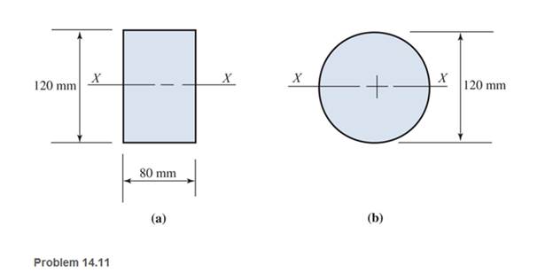
The beams of cross sections shown are subjected to a total shear force of
Expert Solution & Answer

Learn your wayIncludes step-by-step video

schedule04:34
Students have asked these similar questions
Calculate the maximum normal and shear stress values for the attached beam at x = 8.5 m.
Determine the distribution of the shear stress in the cross-section in the y-axis direction at y=55 mm, y=109.99 mm and y=110.01 from top.
The dimensions of the beam are a = 5.5 m, b = 3.0 m and c = 2.5 m, and the cross-sectional dimensions are d = 170 mm and h = 130 mm. The distributed load of the beam has the value q = 3kN / m and the force F = 10kN.
A wide flange beam as shown below is subjected to a shear force V. Using the dimensions of the cross section, determine the following quantities:
a. τmax in the webb. τmin in the webc. τmax/ τaverage of the web
Determine the normal stress and shear stress at a point distant from hP from the bottom surface of the depicted cross, also determine the maximum normal stress and maximum shear stress in the cross section.
t=10 mm
w= 150 mm
h=180 mm
V= 5 kN
M= 3 kN.m
hP= 145 mm
Chapter 14 Solutions
Applied Statics and Strength of Materials (6th Edition)
Ch. 14 - Calculate the section modulus for: (a) a 6 -in-by-...Ch. 14 - Calculate the section modulus (with respect to the...Ch. 14 - Prob. 14.3PCh. 14 - Rework Problem 14.3 changing the orientation of...Ch. 14 - Assume that the timber member (a) of Problem 14.2...Ch. 14 - The structural steel built-up member (b) of...Ch. 14 - A round steel rod, 25 mm in diameter, is subjected...Ch. 14 - A square steel bar, 38 mm on each side, is used as...Ch. 14 - Calculate the moment strength for a W36302...Ch. 14 - Calculate the allowable bending moment for a solid...
Ch. 14 - The beams of cross sections shown are subjected to...Ch. 14 - A solid rectangular simply supported timber beam 6...Ch. 14 - A W1430 supports the loads shown. Calculate the...Ch. 14 - If the allowable shear stress is 100 MPa,...Ch. 14 - A steel pin 112 in diameter is subjected to a...Ch. 14 - A timber power-line pole is 10 in. in diameter at...Ch. 14 - Calculate the value of S and Z and the shape...Ch. 14 - For beams that have cross sections as shown for...Ch. 14 - Calculate the maximum load P that the beam shown...Ch. 14 - A 412 (S4S) hem-fir timber beam carries a...Ch. 14 - A simply supported W1636 A992 steel beam carries a...Ch. 14 - A W250115 steel wide-flange section supports a...Ch. 14 - Assume that the floor joist dimensions of Example...Ch. 14 - Calculate the allowable superimposed uniformly...Ch. 14 - A 3 -in.-by- 12 -in. (S4S) scaffold timber plank...Ch. 14 - For the following computer problems, any...Ch. 14 - For the following computer problems, any...Ch. 14 - For the following computer problems, any...Ch. 14 - Calculate the section modulus with respect to the...Ch. 14 - The timber box section (a) of Problem 14.29 is...Ch. 14 - A timber beam is subjected to a maximum bending...Ch. 14 - Rework Problem 14.31 assuming that the beam is...Ch. 14 - A 12 -in.-diameter steel rod projects 2 ft...Ch. 14 - Calculate the maximum bending stress in a W530101...Ch. 14 - A cantilever cast-iron beam is 6 ft long and has a...Ch. 14 - 14.36 Calculate the moment strength for a...Ch. 14 - A W813 steel wide-flange beam on a 20 -ft span is...Ch. 14 - A simply supported beam with a cruciform cross...Ch. 14 - A rectangular beam 100 mm in width and 250 mm in...Ch. 14 - The timber box section (a) of Problem 14.29 is...Ch. 14 - For the I-shaped timber beam shown, calculate the...Ch. 14 - 14.42 A steel wide-flange beam is oriented so that...Ch. 14 - A W1045steel wide-flange beam supports a uniformly...Ch. 14 - 14.44 A steel wide-flange section is subjected to...Ch. 14 - A W30108 steel wide-flange beam is simply...Ch. 14 - A W612 is strengthened with a 34 -in.-by- 34 -in....Ch. 14 - Four wood boards 1 in. by 6 in. in cross section...Ch. 14 - A lintel consists of two 8 -in.-by- 12 in. steel...Ch. 14 - A 50 -mm-by- 300 -mm scaffold timber plank, placed...Ch. 14 - A laminated wood beam is built up by gluing...Ch. 14 - A rectangular hollow shape carries loads as shown....Ch. 14 - For the beam shown, calculate the maximum tensile...Ch. 14 - 14.53 A box beam is built up of four -in.-by--in....Ch. 14 - 14.54 Find the value of the loads P that can be...Ch. 14 - 14.55 Solve Problem 14.54 assuming that the timber...Ch. 14 - Calculate the values of S and Z and the shape...Ch. 14 - 14.57 A is supported on simple supports on a -ft...
Additional Engineering Textbook Solutions
Find more solutions based on key concepts
Determine the position of the particle when t = 6 s and the total distance it travels during the 6-s time inter...
Engineering Mechanics: Dynamics (14th Edition)
The man having a weight of 200 Ib pushes horizontally on the crate. If the coefficient of static friction betwe...
INTERNATIONAL EDITION---Engineering Mechanics: Statics, 14th edition (SI unit)
A cube has side dimensions of 18.00 in. It is made of steel having a specific weight of 491lb/ft3. What force i...
Applied Fluid Mechanics (7th Edition)
The moments of inertia Iu,Iv and the product of inertia Iuv for the rectangular area.
Engineering Mechanics: Statics & Dynamics (14th Edition)
If FB = 30 lb and FC = 45 lb, determine the resultant moment about the bolt located at A. Probs. 49/10
Engineering Mechanics: Statics
What parts are included in the vehicle chassis?
Automotive Technology: Principles, Diagnosis, and Service (5th Edition)
Knowledge Booster


Learn more about
Need a deep-dive on the concept behind this application? Look no further. Learn more about this topic, mechanical-engineering and related others by exploring similar questions and additional content below.Similar questions
- If the simply supported beam is subjected to the load shown below, determine the following: c- c - The internal bending moment acting on the cross-section through point C. d- d- The shear stress at section C.arrow_forwardA wooden beam is fabricated by bolting together three members as shown. The 8-mm- diameter bolts are spaced at intervals of s= 200 mm along the x axis of the beam. If the internal shear force in the beam is V=7 kN, determine the shear stress in each bolt. 40 mm 40 mm 90 mm 40 mm 300 mmarrow_forwardIf M = 1 kip # ft, determine the resultant force the bending stresses produce on the top board A of the beam.arrow_forward
- The structure shown consists of a single member ABCDE with a pin support at A and a roller support at E. Points B and D are at the midpoints of their respective segments. Determine the internal shear force acting on I which are located immediately to the left of C. Take N = 1 kN, O = 3 kN, and P = 4 kN.arrow_forward1. kN along Z-axis and a shear force of 2 kN along Y-axis. The other end of the axle is fixed to a rigid wall. 1) Calculate all internal loadings on the cross section through the point A. 2) Calculate the stress at point A due to each internal loading. The solid axle has a diameter of 40 mm. It is subjected to a shear force of 1 centroid of a semicircular area, radius =r 4r Rigid Wall 1 kN 0.4 m 2 kNarrow_forwardDetermine the internal shear force at a location of x = 4.2 m for the following beam in kN. 3m 5 KN f(x) = 2 (kN/m) 5marrow_forward
- Determine the internal shear force at a location of x = 0.3 m for the following beam in kN. 3m 8 kN 4 m Xarrow_forwardThe T-beam is subjected to the loading shown. Determine the maximum transverse shear stress in the beam at the critical section. A 2 m 20 kN 2 m 8 kN/m 3 m B 100 mm 100 mm 20 mm 20 mmarrow_forward50 mm 100 mmarrow_forward
- Find the second moment of area, the location of the neutral axis, and the distances from the neutral axis to the top and bottom surfaces. Consider that the section is transmitting a positive bending moment about the z axis, Mz, where M₂ = 10 kip-in if the dimensions of the section are given in ips units, or M₂ = 1.13 kN·m if the dimensions are in Sl units. Determine the resulting stresses at the top and bottom surfaces and at every abrupt change in the cross section. From the figure Z 1 in 112 in y in → ← ¹ in 12 in D C B A ++ in The area is determined to be 2.0625 in². The distances from the neutral axis to the top and bottom surfaces are determined to be 0.858 x in and The second moment of area is determined to be 0.447 in 4. 1.017 xin.arrow_forward1. The wide-flange beam is subjected to a shear force of V = 20 kN. Determine the shear stress distribution in the beam.arrow_forwardFind the second moment of area, the location of the neutral axis, and the distances from the neutral axis to the top and bottom surfaces. Consider that the section is transmitting a positive bending moment about the z axis, Mz, where M₂ = 10 kip-in if the dimensions of the section are given in ips units, or M₂ = 1.13 kN·m if the dimensions are in Sl units. Determine the resulting stresses at the top and bottom surfaces and at every abrupt change in the cross section. From the figure, с - 12.5 B A y I 50 100 75 12.5- 12.5 25 D 100 The area is determined to be 3750 mm² The distances from the neutral axis to the top and bottom surfaces are determined to be 57.292 The second moment of area is determined to be 4.293 x 106 mm4. mm and 42.708 ✪ mm.arrow_forward
arrow_back_ios
SEE MORE QUESTIONS
arrow_forward_ios
Recommended textbooks for you
 Elements Of ElectromagneticsMechanical EngineeringISBN:9780190698614Author:Sadiku, Matthew N. O.Publisher:Oxford University Press
 Mechanics of Materials (10th Edition)Mechanical EngineeringISBN:9780134319650Author:Russell C. HibbelerPublisher:PEARSON
 Thermodynamics: An Engineering ApproachMechanical EngineeringISBN:9781259822674Author:Yunus A. Cengel Dr., Michael A. BolesPublisher:McGraw-Hill Education
 Control Systems EngineeringMechanical EngineeringISBN:9781118170519Author:Norman S. NisePublisher:WILEY
 Mechanics of Materials (MindTap Course List)Mechanical EngineeringISBN:9781337093347Author:Barry J. Goodno, James M. GerePublisher:Cengage Learning
 Engineering Mechanics: StaticsMechanical EngineeringISBN:9781118807330Author:James L. Meriam, L. G. Kraige, J. N. BoltonPublisher:WILEY
Elements Of Electromagnetics
Mechanical Engineering
ISBN:9780190698614
Author:Sadiku, Matthew N. O.
Publisher:Oxford University Press
Mechanics of Materials (10th Edition)
Mechanical Engineering
ISBN:9780134319650
Author:Russell C. Hibbeler
Publisher:PEARSON
Thermodynamics: An Engineering Approach
Mechanical Engineering
ISBN:9781259822674
Author:Yunus A. Cengel Dr., Michael A. Boles
Publisher:McGraw-Hill Education
Control Systems Engineering
Mechanical Engineering
ISBN:9781118170519
Author:Norman S. Nise
Publisher:WILEY
Mechanics of Materials (MindTap Course List)
Mechanical Engineering
ISBN:9781337093347
Author:Barry J. Goodno, James M. Gere
Publisher:Cengage Learning
Engineering Mechanics: Statics
Mechanical Engineering
ISBN:9781118807330
Author:James L. Meriam, L. G. Kraige, J. N. Bolton
Publisher:WILEY
Understanding Shear Force and Bending Moment Diagrams; Author: The Efficient Engineer;https://www.youtube.com/watch?v=C-FEVzI8oe8;License: Standard YouTube License, CC-BY
Bending Stress; Author: moodlemech;https://www.youtube.com/watch?v=9QIqewkE6xM;License: Standard Youtube License