
Applied Statics and Strength of Materials (6th Edition)
6th Edition
ISBN: 9780133840544
Author: George F. Limbrunner, Craig D'Allaird, Leonard Spiegel
Publisher: PEARSON
expand_more
expand_more
format_list_bulleted
Videos
Textbook Question
Chapter 14, Problem 14.50SP
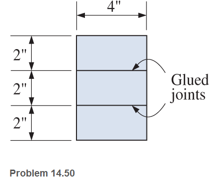
A laminated wood beam is built up by gluing together three
(a) Calculate the maximum allowable load P that can be applied at the free end.
(b) Calculate the maximum bending stress in the beam.
Expert Solution & Answer
Want to see the full answer?
Check out a sample textbook solution
Students have asked these similar questions
Aluminum
10K
12'
Steel
A 12' long beam in supported by an aluminum hanger at
A and by a steel hanger at B. The beam carries a single
10K concentrated load. Neglect the self-weight of the
beam. Both hangers have the same original length.
Ealum = 10,000,000 psi
Esteel = 29,000,000 psi
If the load is located at midspan, and the steel hanger is
a 1/2" x 1/2" bar, what is the width of the 1/2" aluminum
bar, such that points A and B lie on the same horizontal
line?
Typically, an aircraft wing is supported by a single structural spar attached to the main fuselage at the wing root as
shown. This arrangement can be idealized as a cantilever beam with a loading distribution characterizing wing pressure.
In general, holes are introduced to the structural members to reduce the overall weight of the wing (observe the rib
sections shown in B). For the idealized beam arrangement (shown in the C), assume that the cross section of the spar is
uniform and has a rectangular cross section (2" x 16"). The material is 2016-T6 Aluminum.
If four 7" diameter holes are introduced to the beam (as shown in C, below), what is the maximum increase in normal
stress? Ignore the effect of transverse shear.
(A)
(C)
Wing Root
(Assumed Fixed)
80 lb/in
1.8'
1.8'
(B)
1.8'
9'
Wing Root
+
1.8'
W
Wing Tip
Fuel Tank
Wing Tip
(Assumed Free)
The beam shown will be constructed from a standard steel W-shape using an allowable bending stress of 40.4 ksi. Assume P = 51 kips, L1=6.6 ft, and L2=19.8 ft.
(a) Determine the minimum section modulus required for this beam.
(b) From the table below, select the lightest W shape that can be used for this beam.
(c) What is the total weight of the steel beam itself (i.e., not including the loads that are carried by the beam)?
Chapter 14 Solutions
Applied Statics and Strength of Materials (6th Edition)
Ch. 14 - Calculate the section modulus for: (a) a 6 -in-by-...Ch. 14 - Calculate the section modulus (with respect to the...Ch. 14 - Prob. 14.3PCh. 14 - Rework Problem 14.3 changing the orientation of...Ch. 14 - Assume that the timber member (a) of Problem 14.2...Ch. 14 - The structural steel built-up member (b) of...Ch. 14 - A round steel rod, 25 mm in diameter, is subjected...Ch. 14 - A square steel bar, 38 mm on each side, is used as...Ch. 14 - Calculate the moment strength for a W36302...Ch. 14 - Calculate the allowable bending moment for a solid...
Ch. 14 - The beams of cross sections shown are subjected to...Ch. 14 - A solid rectangular simply supported timber beam 6...Ch. 14 - A W1430 supports the loads shown. Calculate the...Ch. 14 - If the allowable shear stress is 100 MPa,...Ch. 14 - A steel pin 112 in diameter is subjected to a...Ch. 14 - A timber power-line pole is 10 in. in diameter at...Ch. 14 - Calculate the value of S and Z and the shape...Ch. 14 - For beams that have cross sections as shown for...Ch. 14 - Calculate the maximum load P that the beam shown...Ch. 14 - A 412 (S4S) hem-fir timber beam carries a...Ch. 14 - A simply supported W1636 A992 steel beam carries a...Ch. 14 - A W250115 steel wide-flange section supports a...Ch. 14 - Assume that the floor joist dimensions of Example...Ch. 14 - Calculate the allowable superimposed uniformly...Ch. 14 - A 3 -in.-by- 12 -in. (S4S) scaffold timber plank...Ch. 14 - For the following computer problems, any...Ch. 14 - For the following computer problems, any...Ch. 14 - For the following computer problems, any...Ch. 14 - Calculate the section modulus with respect to the...Ch. 14 - The timber box section (a) of Problem 14.29 is...Ch. 14 - A timber beam is subjected to a maximum bending...Ch. 14 - Rework Problem 14.31 assuming that the beam is...Ch. 14 - A 12 -in.-diameter steel rod projects 2 ft...Ch. 14 - Calculate the maximum bending stress in a W530101...Ch. 14 - A cantilever cast-iron beam is 6 ft long and has a...Ch. 14 - 14.36 Calculate the moment strength for a...Ch. 14 - A W813 steel wide-flange beam on a 20 -ft span is...Ch. 14 - A simply supported beam with a cruciform cross...Ch. 14 - A rectangular beam 100 mm in width and 250 mm in...Ch. 14 - The timber box section (a) of Problem 14.29 is...Ch. 14 - For the I-shaped timber beam shown, calculate the...Ch. 14 - 14.42 A steel wide-flange beam is oriented so that...Ch. 14 - A W1045steel wide-flange beam supports a uniformly...Ch. 14 - 14.44 A steel wide-flange section is subjected to...Ch. 14 - A W30108 steel wide-flange beam is simply...Ch. 14 - A W612 is strengthened with a 34 -in.-by- 34 -in....Ch. 14 - Four wood boards 1 in. by 6 in. in cross section...Ch. 14 - A lintel consists of two 8 -in.-by- 12 in. steel...Ch. 14 - A 50 -mm-by- 300 -mm scaffold timber plank, placed...Ch. 14 - A laminated wood beam is built up by gluing...Ch. 14 - A rectangular hollow shape carries loads as shown....Ch. 14 - For the beam shown, calculate the maximum tensile...Ch. 14 - 14.53 A box beam is built up of four -in.-by--in....Ch. 14 - 14.54 Find the value of the loads P that can be...Ch. 14 - 14.55 Solve Problem 14.54 assuming that the timber...Ch. 14 - Calculate the values of S and Z and the shape...Ch. 14 - 14.57 A is supported on simple supports on a -ft...
Knowledge Booster


Learn more about
Need a deep-dive on the concept behind this application? Look no further. Learn more about this topic, mechanical-engineering and related others by exploring similar questions and additional content below.Similar questions
- Draw the (a) axial (b) shear and (c) bending moment diagram of the girders. Use Factor Method for structure (3). All columns have the same area. The beams and columns have the same modulus of elasticity. Assume moment inertia of beams is twice the moment of inertia of columns.arrow_forwardA 4-m long simply supported beam has a section modulus of 1408 x 10³ mm³. The allowable stress in the beam is not to exceed 100MPa. The maximum distributed load that the beam can carry is most nearly,arrow_forwardAlaminated beam is composed of three planks, each 150mm. by 60mm, glued together to form a section 150mm wide by 180mm high. The allowable shear stress in the glue is 600kPa, the allowable shear stress in the wood is gook Pa, and the allowable flexure stress in the wood is 8 MPa. Determine the maximum uniformly distributed load which can be carried by the beam on a 2-m simple span.arrow_forward
- A simply supported wood beam with a span of L-8 ft supports a uniformly distributed load w. The beam width is b-7 in, and the beam height is h-14 in. The allowable bending stress of the wood is 1110 psi. Determine the magnitude of the maximum load w that may be carried by the beam Answer: wi 1 lb/ft.arrow_forwarda rectangular beam with a span of 20ft is simply supported at both ends. The maximum flexural stress for the beam is 1200 psi and the dimensions of its cross-section are: b=4 in and h=10 in. If the beam is to be loaded at mid-span with a concentrated load of 2000lbs, will the beam collapse?arrow_forwardQ3) Answer (a) or (b) for the following: (a) A continuous beam ABCD is simply supported over three spans AB = 1m, BC = 2m, and CD = 2m. The first span carries a central load of 20kN and the third span a uniformly distributed load of 30kN/m. The central span remains unloaded. Calculate the bending moments at B and C and draw the S.F. and B.M. diagrams. (b) A 5m long cantilever ABC is built-in at A, partially supported at B, 3m from A, with a force of 15kN and carries a vertical load of 30kN at C, a uniformly distributed load of 10kN.m is also applied between A and B. Draw S.F. and B. M. diagrams of the beam, also compute the deflection of the free end C of the cantilever. Take EI = 8×10⁷ N.m². دامهarrow_forward
- 4. A simply supported beam with a span of 5 m is built with the isolated T-section shown in Fig. (4). The beam is used to support a uniformly distributed dead load (including self-weight) of 20 kN/m and uniformly distributed live load of 25 kN/m. If the simply supported beam is part of floor attached to partition not likely to be damaged by the deflection, check if the deflection in the beam within the permissible limits of ACI318 code? ( Assume 20% of the live load is sustained after 5- years). Given: fc=21 MPa, and f,=420 MPa, and n = 9. 700 mm |75 mm Stirrups #10 5#32 400 mm 300 mm Fig. (4)arrow_forwardI Review The simply-supported beam is built-up from three boards by nailing them together as shown. The wood has an allowable shear stress of Tallow = 1.5 MPa, and an allowable bending stress of oallow = 9 MPa. The nails are spaced at s = 77 mm, and each has a shear strength of 1.5 kN. (Figure 1) %3D Part A Determine the maximum allowable force P that can be applied to the beam. Express your answer to three significant figures and include the appropriate units. HA ? P= 8.9 kN Submit Previous Answers Request Answer X Incorrect; Try Again; 3 attempts remaining Provide Feedback Next > Figure < 1 of 1 P. B 1m 1m 100 mm 25 mm 25 mm 200 mm 25 mmarrow_forwardMoment diagrams. 14. (a) A timber beam of rectangular section is to support a load of 20KN/M uniformly distributed ou a span of 3.6 m. If the depth of the section is to be twice the width and the stress in the sm is not to exceed 7N/mm2. find the dimensions of the beam. (or) (b) A timber beam 150x 300 mm in section, supports a central point load on a span of 4 m. If the max bending stress is 8 N/mm2, what is the max deflection. Take E=0.1x 10 N/mm2 alanod bu a hallow shaft. The ratio external dia to internalarrow_forward
- Problem 2: For the beam and loading shown: 1) determine the reactions at A and B. 2) draw the shear diagram, 3) draw the moment diagram, 4) calculate the maximum bending moment, 5) calculate the maximum stress. Data: h= 12 in 400 Th/ft 8 ft 4.5 kips 3.5 in. Tarrow_forwardA cantilever wood beam consists of eight 2 in. thick planks glued together to form a cross section that is 16 in. deep. Each plank has a width of b = 6.7 in. The cantilever beam has a length of L = 7.3 ft and it supports a concentrated load of P = 3600 lb. (a) Calculate the magnitude of the horizontal shear stress at points A, B, C, and D. (b) From these results, plot a graph showing the distribution of shear stresses from top to bottom of the beam. A 2 in. (typ) y B 16 in. L b Answer: ТА psi TR = i psi Tc = psi Ip = i psiarrow_forward2. For the 20 meter beam shown, there is a roller at "A" (Ay = 52 kN; it is acting upward), and a pin joint at "B" (By=-- 17 kN; it is acting downward). (a) Draw complete shear force and bending moment diagrams. (b) If x=0 is at the left end of the beam, write equations for the shear force and bending moment, and indicate the appropriate sections. (You may use the table on the next page.) 50 KN 15 KN A 90 kN-m 2 m3 m -5 m B *4 -7 m 120 kN-m € 3 marrow_forward
arrow_back_ios
SEE MORE QUESTIONS
arrow_forward_ios
Recommended textbooks for you
 Mechanics of Materials (MindTap Course List)Mechanical EngineeringISBN:9781337093347Author:Barry J. Goodno, James M. GerePublisher:Cengage Learning
Mechanics of Materials (MindTap Course List)
Mechanical Engineering
ISBN:9781337093347
Author:Barry J. Goodno, James M. Gere
Publisher:Cengage Learning
Mechanics of Materials Lecture: Beam Design; Author: UWMC Engineering;https://www.youtube.com/watch?v=-wVs5pvQPm4;License: Standard Youtube License