
Applied Statics and Strength of Materials (6th Edition)
6th Edition
ISBN: 9780133840544
Author: George F. Limbrunner, Craig D'Allaird, Leonard Spiegel
Publisher: PEARSON
expand_more
expand_more
format_list_bulleted
Concept explainers
Videos
Textbook Question
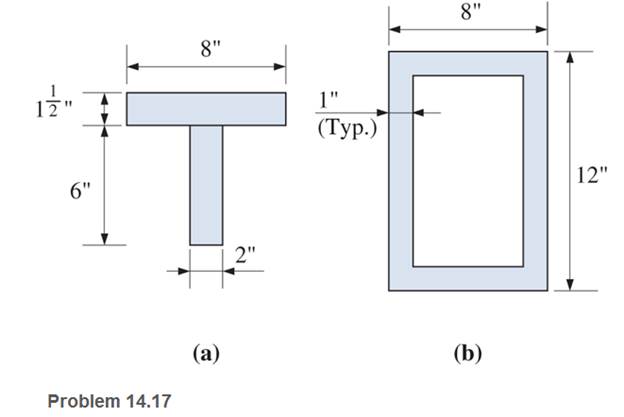
Chapter 14, Problem 14.17P
Calculate the value of S and Z and the shape factor for the beam cross sections shown.
Expert Solution & Answer
Want to see the full answer?
Check out a sample textbook solution
Students have asked these similar questions
Calculate the modulus of section of rectangle beam of breadth 120 mm and height 200 mm.
Calculate the shear force and bending moment in each beam at sections 1-1, 2-2 and 3-3.
Calculate the normal stress, shear stress, and bending deformation of the beam. (Point A has a pinned support, while point C has a roller support)
Chapter 14 Solutions
Applied Statics and Strength of Materials (6th Edition)
Ch. 14 - Calculate the section modulus for: (a) a 6 -in-by-...Ch. 14 - Calculate the section modulus (with respect to the...Ch. 14 - Prob. 14.3PCh. 14 - Rework Problem 14.3 changing the orientation of...Ch. 14 - Assume that the timber member (a) of Problem 14.2...Ch. 14 - The structural steel built-up member (b) of...Ch. 14 - A round steel rod, 25 mm in diameter, is subjected...Ch. 14 - A square steel bar, 38 mm on each side, is used as...Ch. 14 - Calculate the moment strength for a W36302...Ch. 14 - Calculate the allowable bending moment for a solid...
Ch. 14 - The beams of cross sections shown are subjected to...Ch. 14 - A solid rectangular simply supported timber beam 6...Ch. 14 - A W1430 supports the loads shown. Calculate the...Ch. 14 - If the allowable shear stress is 100 MPa,...Ch. 14 - A steel pin 112 in diameter is subjected to a...Ch. 14 - A timber power-line pole is 10 in. in diameter at...Ch. 14 - Calculate the value of S and Z and the shape...Ch. 14 - For beams that have cross sections as shown for...Ch. 14 - Calculate the maximum load P that the beam shown...Ch. 14 - A 412 (S4S) hem-fir timber beam carries a...Ch. 14 - A simply supported W1636 A992 steel beam carries a...Ch. 14 - A W250115 steel wide-flange section supports a...Ch. 14 - Assume that the floor joist dimensions of Example...Ch. 14 - Calculate the allowable superimposed uniformly...Ch. 14 - A 3 -in.-by- 12 -in. (S4S) scaffold timber plank...Ch. 14 - For the following computer problems, any...Ch. 14 - For the following computer problems, any...Ch. 14 - For the following computer problems, any...Ch. 14 - Calculate the section modulus with respect to the...Ch. 14 - The timber box section (a) of Problem 14.29 is...Ch. 14 - A timber beam is subjected to a maximum bending...Ch. 14 - Rework Problem 14.31 assuming that the beam is...Ch. 14 - A 12 -in.-diameter steel rod projects 2 ft...Ch. 14 - Calculate the maximum bending stress in a W530101...Ch. 14 - A cantilever cast-iron beam is 6 ft long and has a...Ch. 14 - 14.36 Calculate the moment strength for a...Ch. 14 - A W813 steel wide-flange beam on a 20 -ft span is...Ch. 14 - A simply supported beam with a cruciform cross...Ch. 14 - A rectangular beam 100 mm in width and 250 mm in...Ch. 14 - The timber box section (a) of Problem 14.29 is...Ch. 14 - For the I-shaped timber beam shown, calculate the...Ch. 14 - 14.42 A steel wide-flange beam is oriented so that...Ch. 14 - A W1045steel wide-flange beam supports a uniformly...Ch. 14 - 14.44 A steel wide-flange section is subjected to...Ch. 14 - A W30108 steel wide-flange beam is simply...Ch. 14 - A W612 is strengthened with a 34 -in.-by- 34 -in....Ch. 14 - Four wood boards 1 in. by 6 in. in cross section...Ch. 14 - A lintel consists of two 8 -in.-by- 12 in. steel...Ch. 14 - A 50 -mm-by- 300 -mm scaffold timber plank, placed...Ch. 14 - A laminated wood beam is built up by gluing...Ch. 14 - A rectangular hollow shape carries loads as shown....Ch. 14 - For the beam shown, calculate the maximum tensile...Ch. 14 - 14.53 A box beam is built up of four -in.-by--in....Ch. 14 - 14.54 Find the value of the loads P that can be...Ch. 14 - 14.55 Solve Problem 14.54 assuming that the timber...Ch. 14 - Calculate the values of S and Z and the shape...Ch. 14 - 14.57 A is supported on simple supports on a -ft...
Knowledge Booster


Learn more about
Need a deep-dive on the concept behind this application? Look no further. Learn more about this topic, mechanical-engineering and related others by exploring similar questions and additional content below.Similar questions
- Draw the (a) axial (b) shear and (c) bending moment diagram of the girders. Use Factor Method for structure (3). All columns have the same area. The beams and columns have the same modulus of elasticity. Assume moment inertia of beams is twice the moment of inertia of columns.arrow_forward1. The cantilever beam in Figure 1 is fixed at A, and is loaded with a distributed load from A to B and a concentrated moment at C. Use the GRAPHICAL METHOD to plot the shear force and bending moment diagrams for the entire length of the beam. Label values at all key locations on the plots (at changes in loads, maxima, minima, and zeroes). Annotate your diagrams to explain how they were drawn (e.g. "AQAB = (-12 kN/m)(1 m) = -12 kN" and "(dQ/dx)AB = -12 kN/m"). 12 kN/m 5 kNm ZA B D 1 m 0.5 m 0.5 m Figure 1.arrow_forwardFor the beam shown, derive the expressions for V and M, and draw the shear force and bending moment diagrams. Calculate the shear force V and bending moment M at a cross section located 0.5 m from the fixed support. Neglect the weight of the beam. (Show complete calculation and step by step process. Show free body diagram)arrow_forward
- Typically, an aircraft wing is supported by a single structural spar attached to the main fuselage at the wing root as shown. This arrangement can be idealized as a cantilever beam with a loading distribution characterizing wing pressure. In general, holes are introduced to the structural members to reduce the overall weight of the wing (observe the rib sections shown in B). For the idealized beam arrangement (shown in the C), assume that the cross section of the spar is uniform and has a rectangular cross section (2" x 16"). The material is 2016-T6 Aluminum. If four 7" diameter holes are introduced to the beam (as shown in C, below), what is the maximum increase in normal stress? Ignore the effect of transverse shear. (A) (C) Wing Root (Assumed Fixed) 80 lb/in 1.8' 1.8' (B) 1.8' 9' Wing Root + 1.8' W Wing Tip Fuel Tank Wing Tip (Assumed Free)arrow_forwardFor the beam shown on the picture select the corresponding shear force and bending moment diagrams from belowarrow_forwardThe cantilever beam shown is subjected to a concentrated load of P=70800 lb. The cross-sectional dimensions and the moment of inertia of the W16x57 wide-flange shape are: d = 16.4 in. tw=0.430 in. by=7.12 in. ty=0.715 in. 1₂-758 in.4 Compute the value of the shear stress at point H, located at y = 4.8 in. below the centroidal xis. H Answer: Shear stress = psiarrow_forward
- A beam with the cross section indicated below is subject to the loading a - plot the shear forcce diagram and the bending moment diagram for the whole beam using 'method of sections'. Draw the important body diagram for every cut segment and derive paramteric equationsarrow_forwardConstruct the bending moment (M) and shearing force diagram for the beam dimensionsarrow_forwardFor the beam loaded as shown in figure, the maximum bending moment will appeararrow_forward
- From the given beam shown below, compute the following: 20 mm 80 mm 160 mm NA 1.0 m 1.0m H– 20 mm 1. Distance between top of the beam to Neutral Axis or "c top". 2. Moment of Inertia at Neutral Axis or "I" 3. What is the maximum safe value of P if the working stress in shear is 6 MPa? 4. Using the maximum safe value of P what is the Maximum shear? 5. Using the maximum safe value of P what is the Maximum Moment?arrow_forwardFor the beam shown, find the reactions at the supports and plot the shear-force and bending-moment diagrams. Label the diagrams properly and provide values at all key points.arrow_forwardThe beam is supported by a pin at point A and a roller at point C. A distributed load is applied to the beam. Neglect the weight and thickness of the beam. Hints: 1. will need to use similar triangles to find the height after sectioning at B. 2. Review direction of normal force, shear force and bending moment and which is positive or negative. W2 W1 A di d2 Values for the figure are given in the following table. Note the figure may not be to scale. Variable Value W1 190 N-m W2 440 N-m di 5 m d2 5 m a. Determine the magnitude of the normal force at point B, NB. . b. Determine the magnitude of the shear force at point B, VB- c. Is the shear force VB a positive or negative shear force? d. Determine the magnitude of the bending moment at point B, MB. e. Is the bending moment MB a positive or negative bending moment? Round your final answers to 3 significant digits/figures.arrow_forward
arrow_back_ios
SEE MORE QUESTIONS
arrow_forward_ios
Recommended textbooks for you
 Elements Of ElectromagneticsMechanical EngineeringISBN:9780190698614Author:Sadiku, Matthew N. O.Publisher:Oxford University Press
 Mechanics of Materials (10th Edition)Mechanical EngineeringISBN:9780134319650Author:Russell C. HibbelerPublisher:PEARSON
 Thermodynamics: An Engineering ApproachMechanical EngineeringISBN:9781259822674Author:Yunus A. Cengel Dr., Michael A. BolesPublisher:McGraw-Hill Education
 Control Systems EngineeringMechanical EngineeringISBN:9781118170519Author:Norman S. NisePublisher:WILEY
 Mechanics of Materials (MindTap Course List)Mechanical EngineeringISBN:9781337093347Author:Barry J. Goodno, James M. GerePublisher:Cengage Learning
 Engineering Mechanics: StaticsMechanical EngineeringISBN:9781118807330Author:James L. Meriam, L. G. Kraige, J. N. BoltonPublisher:WILEY
Elements Of Electromagnetics
Mechanical Engineering
ISBN:9780190698614
Author:Sadiku, Matthew N. O.
Publisher:Oxford University Press
Mechanics of Materials (10th Edition)
Mechanical Engineering
ISBN:9780134319650
Author:Russell C. Hibbeler
Publisher:PEARSON
Thermodynamics: An Engineering Approach
Mechanical Engineering
ISBN:9781259822674
Author:Yunus A. Cengel Dr., Michael A. Boles
Publisher:McGraw-Hill Education
Control Systems Engineering
Mechanical Engineering
ISBN:9781118170519
Author:Norman S. Nise
Publisher:WILEY
Mechanics of Materials (MindTap Course List)
Mechanical Engineering
ISBN:9781337093347
Author:Barry J. Goodno, James M. Gere
Publisher:Cengage Learning
Engineering Mechanics: Statics
Mechanical Engineering
ISBN:9781118807330
Author:James L. Meriam, L. G. Kraige, J. N. Bolton
Publisher:WILEY
Types of Manufacturing Process | Manufacturing Processes; Author: Magic Marks;https://www.youtube.com/watch?v=koULXptaBTs;License: Standard Youtube License