
Applied Statics and Strength of Materials (6th Edition)
6th Edition
ISBN: 9780133840544
Author: George F. Limbrunner, Craig D'Allaird, Leonard Spiegel
Publisher: PEARSON
expand_more
expand_more
format_list_bulleted
Videos
Textbook Question
Chapter 14, Problem 14.29SP
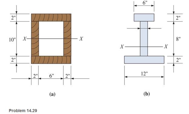
Calculate the section modulus with respect to the X-X axis for the sections shown.
Expert Solution & Answer
Want to see the full answer?
Check out a sample textbook solution
Students have asked these similar questions
Passing an exploratory section through the body and exposing the internal forces acting on the exploratory section, Mxy represents Torsional Moment about x-axis.
Determine the torsional shear stress in the shaft section AB and BC. There is a fixed support at
C that can resist a moment. (Image taken from Statics and Mechanics of Materials by Beer, Johnson, DeWolf and Mazurek)
T₁ = 300 N-m
30 mm
TB = 400 N-m
46 mm
055
Shear Stress in AB =
Shear Stress in BC=
B
0.9 m
0.75 m
units:
units:
The dimensions are of the graph are d1 = 7 cm , L1 = 6 m , d2 = 4.2 cm , and L2 = 5 m with applied loads F1 = 130 kN and F2 = 60 kN . The modulus of elasticity is E = 80 GPa . Use the following steps to find the deflection at point D. Point B is halfway between points A and C.
What is the reaction force at A? Let a positive reaction force be to the right.
Chapter 14 Solutions
Applied Statics and Strength of Materials (6th Edition)
Ch. 14 - Calculate the section modulus for: (a) a 6 -in-by-...Ch. 14 - Calculate the section modulus (with respect to the...Ch. 14 - Prob. 14.3PCh. 14 - Rework Problem 14.3 changing the orientation of...Ch. 14 - Assume that the timber member (a) of Problem 14.2...Ch. 14 - The structural steel built-up member (b) of...Ch. 14 - A round steel rod, 25 mm in diameter, is subjected...Ch. 14 - A square steel bar, 38 mm on each side, is used as...Ch. 14 - Calculate the moment strength for a W36302...Ch. 14 - Calculate the allowable bending moment for a solid...
Ch. 14 - The beams of cross sections shown are subjected to...Ch. 14 - A solid rectangular simply supported timber beam 6...Ch. 14 - A W1430 supports the loads shown. Calculate the...Ch. 14 - If the allowable shear stress is 100 MPa,...Ch. 14 - A steel pin 112 in diameter is subjected to a...Ch. 14 - A timber power-line pole is 10 in. in diameter at...Ch. 14 - Calculate the value of S and Z and the shape...Ch. 14 - For beams that have cross sections as shown for...Ch. 14 - Calculate the maximum load P that the beam shown...Ch. 14 - A 412 (S4S) hem-fir timber beam carries a...Ch. 14 - A simply supported W1636 A992 steel beam carries a...Ch. 14 - A W250115 steel wide-flange section supports a...Ch. 14 - Assume that the floor joist dimensions of Example...Ch. 14 - Calculate the allowable superimposed uniformly...Ch. 14 - A 3 -in.-by- 12 -in. (S4S) scaffold timber plank...Ch. 14 - For the following computer problems, any...Ch. 14 - For the following computer problems, any...Ch. 14 - For the following computer problems, any...Ch. 14 - Calculate the section modulus with respect to the...Ch. 14 - The timber box section (a) of Problem 14.29 is...Ch. 14 - A timber beam is subjected to a maximum bending...Ch. 14 - Rework Problem 14.31 assuming that the beam is...Ch. 14 - A 12 -in.-diameter steel rod projects 2 ft...Ch. 14 - Calculate the maximum bending stress in a W530101...Ch. 14 - A cantilever cast-iron beam is 6 ft long and has a...Ch. 14 - 14.36 Calculate the moment strength for a...Ch. 14 - A W813 steel wide-flange beam on a 20 -ft span is...Ch. 14 - A simply supported beam with a cruciform cross...Ch. 14 - A rectangular beam 100 mm in width and 250 mm in...Ch. 14 - The timber box section (a) of Problem 14.29 is...Ch. 14 - For the I-shaped timber beam shown, calculate the...Ch. 14 - 14.42 A steel wide-flange beam is oriented so that...Ch. 14 - A W1045steel wide-flange beam supports a uniformly...Ch. 14 - 14.44 A steel wide-flange section is subjected to...Ch. 14 - A W30108 steel wide-flange beam is simply...Ch. 14 - A W612 is strengthened with a 34 -in.-by- 34 -in....Ch. 14 - Four wood boards 1 in. by 6 in. in cross section...Ch. 14 - A lintel consists of two 8 -in.-by- 12 in. steel...Ch. 14 - A 50 -mm-by- 300 -mm scaffold timber plank, placed...Ch. 14 - A laminated wood beam is built up by gluing...Ch. 14 - A rectangular hollow shape carries loads as shown....Ch. 14 - For the beam shown, calculate the maximum tensile...Ch. 14 - 14.53 A box beam is built up of four -in.-by--in....Ch. 14 - 14.54 Find the value of the loads P that can be...Ch. 14 - 14.55 Solve Problem 14.54 assuming that the timber...Ch. 14 - Calculate the values of S and Z and the shape...Ch. 14 - 14.57 A is supported on simple supports on a -ft...
Knowledge Booster


Learn more about
Need a deep-dive on the concept behind this application? Look no further. Learn more about this topic, mechanical-engineering and related others by exploring similar questions and additional content below.Similar questions
- Determine the shape factor f for a cross section in the shape of a double trapezoid having the dimensions shown in the figure. Also, check your result for the special cases of a rhombus (b1= 0) and a rectangle (b1= b2).arrow_forwardDetermine Iu for the inverted T-section shown. Note that the section is symmetric about the y-axis.arrow_forwardThe triangular plate is fixed at its base, and its apex A is given a horizontal displacement of 5 mm. Suppose that a= 640 mmarrow_forward
- Answer for the 1st part of the problem. magnitude of force A = 74 N direction of force A = 25o north of west second force = P direction of force P = α south of west arrow_forward The resultant of two forces is horizontal , it means that the y component of resultant = 0 Ry = ASin(25o) - PSin(α) 0 = (74×0.42) - PSin(α) PSin(α) = 31.08 NFor, the smallest force P , the value of Sinα must be maximum which is 1 when the value of αis 90 degree Thus, P×Sin(90o) = 31.08 N P = 31.08 N The magnitude of smallest force P = 31.08 N the direction of force P = 90 degree south of west = along - y axis= arrow pointing vertically downwarrow_forwardIf an axis of symmetry for the cross-section exists, the shearthe center lies at a point on this axis.Is it true or false?arrow_forwardProblem: The steel pipe has an inner diameter of 2.75 in and an outer diameter of 3 in. The pipe is fixed to the ground at C, and a wrench is attached to the opposite end. The wrench is subjected to a horizontal force of 20 lb that acts in -z direction. Points A and B are located on the surface of the pipe at the same cross section. Note that A lies directly above the -y axis, and B lies directly above the +z axis. 20 lb 10 in. A B y 12 in. (a) Find the normal and shear stresses at points A and B. (b) Find the principal stresses at points A and B. (c) Show all stresses from parts (a) and (b) on properly oriented elements, relative to the given coordinate system.arrow_forward
- The figure shows a square element with sides parallel to the x y axes. The axis is horizontally rightward. The y axis is vertically upward. Each side of the square is accompanied by normal and shear stress vectors. Normal vertical stress of 100 megapascals is inward. Normal horizontal stress of 30 megapascals is outward. Shear stress vectors of 50 megapascals are directed toward the upper right and lower left vertices of the square.arrow_forwardif the moments at B are 5wL^2/192, where does that formula come from? (Only Handwritten solution Need)arrow_forwardIf the horizontal displacements of nodes 2 and 3 of the following element are q2=0.1 mm and q3=-0.05 mm, respectively what is the horizontal displacement of point "P" located at (§, n) = (1, 0.5) in mm. (-1,1) 4 1 (-1,-1) (1,1) 3 -0.254 Needs more information 0.174 -0.0125 2 (1,-1) 93 XP(1,0.5) { 92arrow_forward
- L,=40mm; L,= 120mm; L=100mm and 0,=65°. Find the possible value of 0, and 0, L,=80mm and 3.arrow_forwardPassing an exploratory section through the body and exposing the internal forces acting on the exploratory section. Mxy represents torsional moment about y-axis. True of Falsearrow_forwardBelow Figure shows the section of an angle purlin. A bending moment of 60 5 kN.m is applied to the purlin in a plane at an angle of 30 deg to the vertical y axis. If the sense of the bending moment is such that both its components Mx and My produce tension in the positive xy quadrant, calculate the maximum direct stress in the purlin, stating clearly the point at which it acts. * 100 mm BỊ 10mm 30° C ID 10mm 57 MPa. 89 MPa. Non Above 72 MPa. 125mmarrow_forward
arrow_back_ios
SEE MORE QUESTIONS
arrow_forward_ios
Recommended textbooks for you
 International Edition---engineering Mechanics: St...Mechanical EngineeringISBN:9781305501607Author:Andrew Pytel And Jaan KiusalaasPublisher:CENGAGE L
 Mechanics of Materials (MindTap Course List)Mechanical EngineeringISBN:9781337093347Author:Barry J. Goodno, James M. GerePublisher:Cengage Learning
International Edition---engineering Mechanics: St...
Mechanical Engineering
ISBN:9781305501607
Author:Andrew Pytel And Jaan Kiusalaas
Publisher:CENGAGE L
Mechanics of Materials (MindTap Course List)
Mechanical Engineering
ISBN:9781337093347
Author:Barry J. Goodno, James M. Gere
Publisher:Cengage Learning
Everything About TRANSVERSE SHEAR in 10 Minutes!! - Mechanics of Materials; Author: Less Boring Lectures;https://www.youtube.com/watch?v=4x0E9yvzfCM;License: Standard Youtube License