
Applied Statics and Strength of Materials (6th Edition)
6th Edition
ISBN: 9780133840544
Author: George F. Limbrunner, Craig D'Allaird, Leonard Spiegel
Publisher: PEARSON
expand_more
expand_more
format_list_bulleted
Concept explainers
Videos
Textbook Question
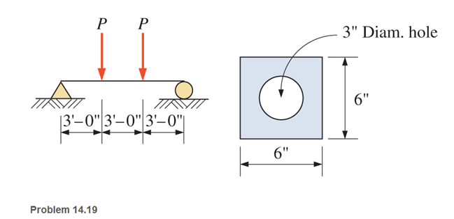
Chapter 14, Problem 14.19P
Calculate the maximum load P that the beam shown can carry based on plastic moment
Expert Solution & Answer
Want to see the full answer?
Check out a sample textbook solution
Students have asked these similar questions
A rectangular bar having width twice the depth is used as a beam. The beam is made of mild steel material having elastic modulus of 2.1 x 10⁵ N/mm? and it
undergoes bending by external load which makes radius of curvature of 150 m.
If the allowable bending stress in the beam is to be limited to 100 MN/m. find the cross section of the beam.
Draw diagrams of shear force and bending moment for beam and loading shown. Calculate the maximum tensile and compressive stresses in the beam.
X=407 N/m
Y=2.21 m
Z=51,4 mm
A beam 8 m span is freely supported at its ends and a udl of 40 KN/m is spread over the
whole span of the beam. In addition a concentrated load of 150 KN is applied at a distance of 3
m from the left support. The section of the beam is 200 mm wide and 400 mm deep. Find the
maximum bending stress induced in the beam section.
Chapter 14 Solutions
Applied Statics and Strength of Materials (6th Edition)
Ch. 14 - Calculate the section modulus for: (a) a 6 -in-by-...Ch. 14 - Calculate the section modulus (with respect to the...Ch. 14 - Prob. 14.3PCh. 14 - Rework Problem 14.3 changing the orientation of...Ch. 14 - Assume that the timber member (a) of Problem 14.2...Ch. 14 - The structural steel built-up member (b) of...Ch. 14 - A round steel rod, 25 mm in diameter, is subjected...Ch. 14 - A square steel bar, 38 mm on each side, is used as...Ch. 14 - Calculate the moment strength for a W36302...Ch. 14 - Calculate the allowable bending moment for a solid...
Ch. 14 - The beams of cross sections shown are subjected to...Ch. 14 - A solid rectangular simply supported timber beam 6...Ch. 14 - A W1430 supports the loads shown. Calculate the...Ch. 14 - If the allowable shear stress is 100 MPa,...Ch. 14 - A steel pin 112 in diameter is subjected to a...Ch. 14 - A timber power-line pole is 10 in. in diameter at...Ch. 14 - Calculate the value of S and Z and the shape...Ch. 14 - For beams that have cross sections as shown for...Ch. 14 - Calculate the maximum load P that the beam shown...Ch. 14 - A 412 (S4S) hem-fir timber beam carries a...Ch. 14 - A simply supported W1636 A992 steel beam carries a...Ch. 14 - A W250115 steel wide-flange section supports a...Ch. 14 - Assume that the floor joist dimensions of Example...Ch. 14 - Calculate the allowable superimposed uniformly...Ch. 14 - A 3 -in.-by- 12 -in. (S4S) scaffold timber plank...Ch. 14 - For the following computer problems, any...Ch. 14 - For the following computer problems, any...Ch. 14 - For the following computer problems, any...Ch. 14 - Calculate the section modulus with respect to the...Ch. 14 - The timber box section (a) of Problem 14.29 is...Ch. 14 - A timber beam is subjected to a maximum bending...Ch. 14 - Rework Problem 14.31 assuming that the beam is...Ch. 14 - A 12 -in.-diameter steel rod projects 2 ft...Ch. 14 - Calculate the maximum bending stress in a W530101...Ch. 14 - A cantilever cast-iron beam is 6 ft long and has a...Ch. 14 - 14.36 Calculate the moment strength for a...Ch. 14 - A W813 steel wide-flange beam on a 20 -ft span is...Ch. 14 - A simply supported beam with a cruciform cross...Ch. 14 - A rectangular beam 100 mm in width and 250 mm in...Ch. 14 - The timber box section (a) of Problem 14.29 is...Ch. 14 - For the I-shaped timber beam shown, calculate the...Ch. 14 - 14.42 A steel wide-flange beam is oriented so that...Ch. 14 - A W1045steel wide-flange beam supports a uniformly...Ch. 14 - 14.44 A steel wide-flange section is subjected to...Ch. 14 - A W30108 steel wide-flange beam is simply...Ch. 14 - A W612 is strengthened with a 34 -in.-by- 34 -in....Ch. 14 - Four wood boards 1 in. by 6 in. in cross section...Ch. 14 - A lintel consists of two 8 -in.-by- 12 in. steel...Ch. 14 - A 50 -mm-by- 300 -mm scaffold timber plank, placed...Ch. 14 - A laminated wood beam is built up by gluing...Ch. 14 - A rectangular hollow shape carries loads as shown....Ch. 14 - For the beam shown, calculate the maximum tensile...Ch. 14 - 14.53 A box beam is built up of four -in.-by--in....Ch. 14 - 14.54 Find the value of the loads P that can be...Ch. 14 - 14.55 Solve Problem 14.54 assuming that the timber...Ch. 14 - Calculate the values of S and Z and the shape...Ch. 14 - 14.57 A is supported on simple supports on a -ft...
Knowledge Booster


Learn more about
Need a deep-dive on the concept behind this application? Look no further. Learn more about this topic, mechanical-engineering and related others by exploring similar questions and additional content below.Similar questions
- Q1 A steel beam of I cross-section is simply supported on a span of 4m. Find the safe uniformly distributed load the beam can carry if the tensile stress is not to exceed (60) N/mm2. Also find the maximum compressive stress.arrow_forwardFind the maximum stress in the beam if it is fixed at the left end,free at the right end subjected to a uniform distributed load of200 lb/in.arrow_forwardCompute the maximum bending moment, maxi- mum deflection and the maximum bending stress for a railroad rail subjected to a single wheel load of 100 kN. The foundation modulus k = 15 MN / m². Assume that I = 400 × 10-8 m², E = 200 GN/m², the depth of the rail is 180 mm and that the distance of the centroidal axis of the cross-section of the rail from the top surface is 100 mm.arrow_forward
- For the beam shown, there is a roller at 1.5 feet from the left and a pinned support at the far-right end. Two loads are applied: a 450-kip vertical load and a 15 kip*ft moment. The cross-sectional shape of the beam is shown on the right. What is the maximum stress on this beam? Note: A kip is a kilopound.arrow_forwardA overhang beam hanged at B(6m) has two loads of 8 & 4 kn at 6 and 9 m. Calulate its moment using castigliano's theorem. Also calculate Strain Energy.arrow_forwardFor the beam shown below, Find the bending stress at point A. 16 50 kN 3 m. 3 marrow_forward
- A cantilever beam of cross-section 90 mm. width 120 mm deep carries a UDL of 12 KN/m. over the entire length and a concentrated load of 15 KN at the right end. Find the bending stress in the beam, when the length of beam is 10 m.arrow_forwardGive me right solution according to the question. Draw the shear force diagram and Bending moment diagrams for the beam clearly.. Take M= 60 KN-m P=30 KNarrow_forward3. Two beams are supported as shown in the diagram below, each 150mm x 200mm x 6 meters. Beam CD is a cantilever beam carrying a uniformly distributed load of 6 KN/m freely supported on beam AB. Beam AB is freely supported on each ends. E = 13.8 GPa for both beam. Neglect the weight of the beam. a. Compute the reaction at D. b. Compute the deflection at D. c. Compute the bending stress of beam CD. 6 ka lm бт 6m 6marrow_forward
- The simple beam shown carries a uniform load w, = 10 kN/m. The dimensions a, b, c, and d are 0.6 m, 0.4 m, 50 mm and 80 mm, respectively. What will be the maximum vertical shear stress in the beam in MPa? d aarrow_forwardFind the maximum bending compressive stress in psi, caused by the load P=1100 lbsarrow_forwardFor the beam shown below, determine the maximum bending stress in the beam. sketch thesection stress distribution.arrow_forward
arrow_back_ios
SEE MORE QUESTIONS
arrow_forward_ios
Recommended textbooks for you
 Elements Of ElectromagneticsMechanical EngineeringISBN:9780190698614Author:Sadiku, Matthew N. O.Publisher:Oxford University Press
 Mechanics of Materials (10th Edition)Mechanical EngineeringISBN:9780134319650Author:Russell C. HibbelerPublisher:PEARSON
 Thermodynamics: An Engineering ApproachMechanical EngineeringISBN:9781259822674Author:Yunus A. Cengel Dr., Michael A. BolesPublisher:McGraw-Hill Education
 Control Systems EngineeringMechanical EngineeringISBN:9781118170519Author:Norman S. NisePublisher:WILEY
 Mechanics of Materials (MindTap Course List)Mechanical EngineeringISBN:9781337093347Author:Barry J. Goodno, James M. GerePublisher:Cengage Learning
 Engineering Mechanics: StaticsMechanical EngineeringISBN:9781118807330Author:James L. Meriam, L. G. Kraige, J. N. BoltonPublisher:WILEY
Elements Of Electromagnetics
Mechanical Engineering
ISBN:9780190698614
Author:Sadiku, Matthew N. O.
Publisher:Oxford University Press
Mechanics of Materials (10th Edition)
Mechanical Engineering
ISBN:9780134319650
Author:Russell C. Hibbeler
Publisher:PEARSON
Thermodynamics: An Engineering Approach
Mechanical Engineering
ISBN:9781259822674
Author:Yunus A. Cengel Dr., Michael A. Boles
Publisher:McGraw-Hill Education
Control Systems Engineering
Mechanical Engineering
ISBN:9781118170519
Author:Norman S. Nise
Publisher:WILEY
Mechanics of Materials (MindTap Course List)
Mechanical Engineering
ISBN:9781337093347
Author:Barry J. Goodno, James M. Gere
Publisher:Cengage Learning
Engineering Mechanics: Statics
Mechanical Engineering
ISBN:9781118807330
Author:James L. Meriam, L. G. Kraige, J. N. Bolton
Publisher:WILEY
Everything About COMBINED LOADING in 10 Minutes! Mechanics of Materials; Author: Less Boring Lectures;https://www.youtube.com/watch?v=N-PlI900hSg;License: Standard youtube license