
Applied Statics and Strength of Materials (6th Edition)
6th Edition
ISBN: 9780133840544
Author: George F. Limbrunner, Craig D'Allaird, Leonard Spiegel
Publisher: PEARSON
expand_more
expand_more
format_list_bulleted
Videos
Textbook Question
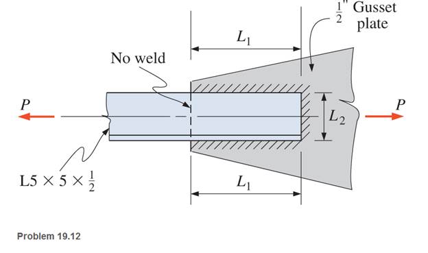
Chapter 19, Problem 19.12P
Design an end connection using longitudinal welds and an end transverse weld to develop the full tensile capacity of the angle shown. Use
Expert Solution & Answer
Want to see the full answer?
Check out a sample textbook solution
Students have asked these similar questions
Using SMAW process, E70 electrodes and an A572 steel. Determine the length of the side fillet welds for the full capacity the 125x100x10mm angle tension member as shown below. Assume that the member is subjected to repeated stress variations making any connection eccentricity undesirable. Check the block shear strength of the member. Assume that the WT chord has sufficient strength to develop the weld strengths and the thickness of its web is 12mm. Use U = 0.87 for class use and LRFD Method only
3.) The diagram below shows a 5.5m long double angle brace which is connected by
6mm welding connection. The length of weld shown in the picture is 300 mm on the
top and 100 mm on the bottom. The 2-L127x 89x6.4 are 300W steel and long leg
back-to-back. The braces are to be welded to a 12 mm 350W steel gusset plate.
Determine the factored tensile capacity of the angles. Any intermediate connections
that are required should also be specified.
740 kN
-12 mm Gusset Plate
Q1: The weldment shown in the figure is subjected to a force F. The hot-rolled steel bar has
a thickness and is of AISI 1040 steel. The vertical support is likewise AISI 1040 HR steel.
The electrode is given in the table below. Estimate the static load F the bar can carry if two
fillet welds are used.
h (mm)
b (mm)
30
d (mm)
70
Elecrode
E8010
Chapter 19 Solutions
Applied Statics and Strength of Materials (6th Edition)
Ch. 19 - Prob. 19.1PCh. 19 - Rework Problem 19.1 assuming a bearing-type...Ch. 19 - Rework Problem 19.1 assuming a bearing-type...Ch. 19 - Compute the allowable tensile load for the...Ch. 19 - Rework Problem 19.4 assuming a bearing-type...Ch. 19 - Rework Problem 19.4 assuming that the bolts are 34...Ch. 19 - Select the number and arrangement of 34 in....Ch. 19 - Calculate the allowable tensile load for the...Ch. 19 - In the connection shown, 14 in. side and end...Ch. 19 - Design the fillet welds parallel to the applied...
Ch. 19 - A fillet weld between two steel plates...Ch. 19 - Design an end connection using longitudinal welds...Ch. 19 - Calculate the allowable tensile load for the butt...Ch. 19 - Calculate the allowable tensile load for the lap...Ch. 19 - Calculate the allowable tensile load for the butt...Ch. 19 - Rework Problem 19.10 assuming that both plates are...Ch. 19 - Rework Problem 19.12 assuming that the angle is an...Ch. 19 - Two ASTM A36 steel plates, each 12 in. by 12 in. ,...Ch. 19 - Rework Problem 19.20 changing the fasteners to 34...Ch. 19 - Calculate the minimum main plate thickness for the...Ch. 19 - A roof truss tension member is made up of 2L6412...Ch. 19 - Rework Problem 19.23 changing the fasteners to six...Ch. 19 - Determine the allowable tensile load that can be...Ch. 19 - The welded connection shown is subjected to an...Ch. 19 - In Problem 19.26, use a 38 in. fillet weld, change...
Knowledge Booster


Learn more about
Need a deep-dive on the concept behind this application? Look no further. Learn more about this topic, mechanical-engineering and related others by exploring similar questions and additional content below.Similar questions
- An angle iron made of AISI 1040 CD steel is welded to metal as shown and loaded with a dynamic load varying between +40kN and +60kN. E70XX (Sut = 482MPa, Sy = 393MPa) will be used as the welding electrode. Find the factor of safety of the weld zone. Note: that both static and dynamic loads are applied to the source.arrow_forwardThe materials for the members being joined in Probs. 9-1 to 9-4 are specified below. What 9-12 load on the weldment is allowable because member metal is incorporated in the welds? Problem Number Reference Problem 9-1 Bar 1018 CD 1035 HR Vertical Support 1018 HR 1035 CDarrow_forwardThe arm in the figure is combined with a rod with a diameter of d=30 mm and a neck (corner) weld with a thickness of a= 5mm to the rod wall.sourced with. The force acting on the arm is F=2 kN. The lengths are L1=L2=100 mm. Joined parts are made of St37-2 (ak=235 N/mm2) material. Welding is I. Quality and has no impact effect. Check if the source in zone A is safe. (S=1.5 V1=0.8)arrow_forward
- Two plates, 25 mm thick, are welded together by means of trans verse-fillet welds. The ultimate tensile strength of a weld metal is 415 MPa. The surface finish factor of the weld surface is 0.5, and the size factor is 0.85. The reliability is 90%. Determine the length of the weld if the factor of safety is 2. The transverse force on the welds is 100 kN, which is completely reversed under fatigue loading. Take: A=10mm 25 Toe Р.arrow_forwardAn axially-loaded welded angular connection is shown SD-002 . The angular section 150 x 100 x 10 mm having an area of 2400 mm? is welded to a gusset plate having a thickness of 10 mm. All steel is A 36 (Fy = 248 MPa, Fu = 400 MPa) and E (70) electrodes (Fu = 484 MPa) is used. Using the shielded metal-arc welding process. Compute the value of "a" if T = 500 kN. (Please do not round-off to whole number the required thickness, use the exact (2 decimal) value.) 150 mm SD-002arrow_forwardProblem 14.3.A A 4 × 4 x 2-in. angle of A36 steel is to be welded to a plate with E 70 XX electrodes to develop the full tensile strength of the angle. Using %-in. fillet welds, compute the design lengths for the welds on the two sides of the angle, assuming development of tension on the full cross sec- tion of the angle. A=3.75 inch2 L1= 10.94" L2 = 5.09" IF only connected leg, L=7.7"; 4.75 each sidearrow_forward
- 4. Design a welded connection to resist the loading shown below (service load). A double angle tension member, 2 L5x5x5/16, is connected to a 3/8 inch thick gusset plate with fillet welding. Fy = 50 ksi for the angles and Fy = 36 ksi for the gusset plate. Compute the size and length of welding on the side of angles based on LRFD and indicate the information on the sketch. 1 = %" 2L5 x 5 x h6 D = 30 k L= 75 karrow_forwardQ1: The weldment shown in the figure is subjected to a force F. The hot-rolled steel bar has a thickness h and is of AISI 1040 steel. The vertical support is likewise AISI 1040 HR steel. The electrode is given in the table below. Estimate the static load F the bar can carry if two fillet welds are used. b (mm) h (mm) d (mm) 70 Elecrode E8010 30 6 1-b- Farrow_forwardFind. The weld sizé W for the welted.join .shawai figure T=2 Nimっ below where aaill =3.MPag Tall=1.5 Mfa F=500 N ..in. D = l00 mm 2 6. =300M m %3D Ans: h=9.1 mm 4s0.707t A TO @ab endingarrow_forward
- Нome work 1. A plate( 100 mm) wide and (10 mm) thick is to be welded with another plate by means of double transverse welds at the ends. If the plates are subjected to a load of (70 kN ), find the size of weld for static as well as fatigue load. The permissible tensile stress should not exceed (70 MPa) [Ans. 83.2 mm; 118.5 mm]arrow_forwardSituation 2: The lap splice shown will develop a full strength as shown in the figure. Using E70 electrodes. The width of the plate is 150 mm and the thickness is 10 mm. Use Fy = 248 MPa T4 46 mm 48 mm 1. Which of the following nearly gives the diameter of the slot weld using the LRFD method. O 45 mm T O 47 mm T Warrow_forward
arrow_back_ios
arrow_forward_ios
Recommended textbooks for you
 Elements Of ElectromagneticsMechanical EngineeringISBN:9780190698614Author:Sadiku, Matthew N. O.Publisher:Oxford University Press
 Mechanics of Materials (10th Edition)Mechanical EngineeringISBN:9780134319650Author:Russell C. HibbelerPublisher:PEARSON
 Thermodynamics: An Engineering ApproachMechanical EngineeringISBN:9781259822674Author:Yunus A. Cengel Dr., Michael A. BolesPublisher:McGraw-Hill Education
 Control Systems EngineeringMechanical EngineeringISBN:9781118170519Author:Norman S. NisePublisher:WILEY
 Mechanics of Materials (MindTap Course List)Mechanical EngineeringISBN:9781337093347Author:Barry J. Goodno, James M. GerePublisher:Cengage Learning
 Engineering Mechanics: StaticsMechanical EngineeringISBN:9781118807330Author:James L. Meriam, L. G. Kraige, J. N. BoltonPublisher:WILEY
Elements Of Electromagnetics
Mechanical Engineering
ISBN:9780190698614
Author:Sadiku, Matthew N. O.
Publisher:Oxford University Press
Mechanics of Materials (10th Edition)
Mechanical Engineering
ISBN:9780134319650
Author:Russell C. Hibbeler
Publisher:PEARSON
Thermodynamics: An Engineering Approach
Mechanical Engineering
ISBN:9781259822674
Author:Yunus A. Cengel Dr., Michael A. Boles
Publisher:McGraw-Hill Education
Control Systems Engineering
Mechanical Engineering
ISBN:9781118170519
Author:Norman S. Nise
Publisher:WILEY
Mechanics of Materials (MindTap Course List)
Mechanical Engineering
ISBN:9781337093347
Author:Barry J. Goodno, James M. Gere
Publisher:Cengage Learning
Engineering Mechanics: Statics
Mechanical Engineering
ISBN:9781118807330
Author:James L. Meriam, L. G. Kraige, J. N. Bolton
Publisher:WILEY
Differences between Temporary Joining and Permanent Joining.; Author: Academic Gain Tutorials;https://www.youtube.com/watch?v=PTr8QZhgXyg;License: Standard Youtube License