
INTERNATIONAL EDITION---Engineering Mechanics: Statics, 14th edition (SI unit)
14th Edition
ISBN: 9780133918922
Author: Russell C. Hibbeler
Publisher: PEARSON
expand_more
expand_more
format_list_bulleted
Concept explainers
Videos
Textbook Question
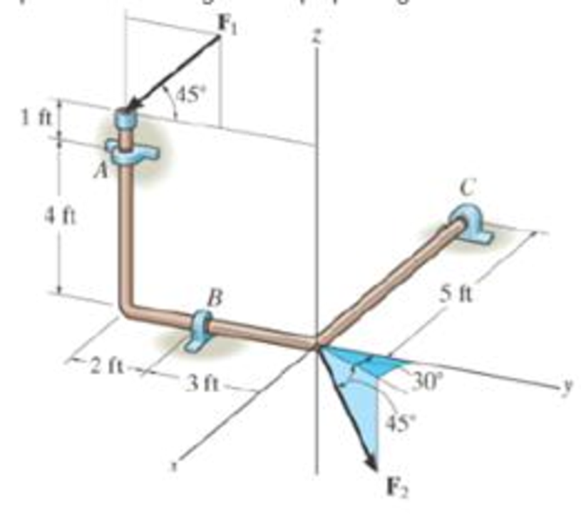
Chapter 5.7, Problem 78P
Compute the x, y, z components of reaction at the bearings. If the rod is subjected to forces F1 = 300 lb and F2 = 250 lb F1 lies n the y-z plane. The bearings are in proper alignment and exert only force reactions on the rod.
Expert Solution & Answer

Learn your wayIncludes step-by-step video

schedule09:45
Students have asked these similar questions
The bent rod is supported at A, B, and C by smooth journal bearings. The rod is subjected to the force F = 620 N . The bearings are in proper alignment and exert only force reactions on the rod.
Determine the components of reaction at the bearing AA using scalar notation.
Determine the components of reaction at the bearing BB using scalar notation.
Determine the components of reaction at the bearing CC using scalar notation.
The dimensions a = 2 m and b = 1 m. The couple M = 2400 N-m. The spring constant is k = 6000 N/m, and the spring would be unstretched if h = 0. The system is in equilibrium when h = 2 m and the beam is horizontal. Determine the force F and thereactions at A.
Determine the reactions at point C and the force in cored AB
30°
В
C
800 lb/ft
-15 ft
-15 ft-
1 Add file
Chapter 5 Solutions
INTERNATIONAL EDITION---Engineering Mechanics: Statics, 14th edition (SI unit)
Ch. 5.2 - Draw the free-body diagram for the following...Ch. 5.2 - Draw the free-body diagram for the following...Ch. 5.2 - Draw the free-body diagram for the following...Ch. 5.2 - Draw the free-body diagram for the following...Ch. 5.2 - Draw the free-body diagram for the following...Ch. 5.2 - Draw the free-body diagram for the following...Ch. 5.2 - Draw the free-body diagram for the following...Ch. 5.2 - Draw the free-body diagram for the following...Ch. 5.2 - Draw the free-body diagram for the following...Ch. 5.4 - Draw the free body diagram of each object. Prob....
Ch. 5.4 - Determine the horizontal and vertical components...Ch. 5.4 - Determine the horizontal and vertical components...Ch. 5.4 - The truss is supported by a pin at A and a roller...Ch. 5.4 - Determine the components of reaction at the fixed...Ch. 5.4 - The 25 kg bar has a center of mass at G. If it is...Ch. 5.4 - Determine the reactions at the smooth contact...Ch. 5.4 - Determine the components of the support reactions...Ch. 5.4 - Determine the reactions at the supports. Prob....Ch. 5.4 - Determine the horizontal and vertical components...Ch. 5.4 - Determine the reactions at the supports. Prob....Ch. 5.4 - Determine the reactions at the supports. Prob....Ch. 5.4 - Determine the reactions at the supports. Prob....Ch. 5.4 - Determine the tension in the cable and the...Ch. 5.4 - The man attempts to a up port the toad of boards...Ch. 5.4 - Determine the components of reaction at the...Ch. 5.4 - The man has a weight W and stands at the center of...Ch. 5.4 - A uniform glass rod having a length L is placed in...Ch. 5.4 - The uniform rod AB has a mass of 40 kg. Determine...Ch. 5.4 - If the intensity of the distributed load acting on...Ch. 5.4 - If the roller at A and the pin at B can support a...Ch. 5.4 - The relay regulates voltage and current. Determine...Ch. 5.4 - Determine the reactions on the bent rod which is...Ch. 5.4 - The mobile crane is symmetrically supported by two...Ch. 5.4 - Determine the reactions acting on the smooth...Ch. 5.4 - A linear torsional spring deforms such that an...Ch. 5.4 - Determine the force P needed to pull the 50-kg...Ch. 5.4 - Determine the magnitude and direction of the...Ch. 5.4 - The operation of the fuel pump for an automobile...Ch. 5.4 - Determine the magnitude of force at the pin A and...Ch. 5.4 - The dimensions of a jib crane, which is...Ch. 5.4 - The dimensions of a jib crane, which is...Ch. 5.4 - The smooth pipe rests against the opening at the...Ch. 5.4 - The beam of negligible weight is supported...Ch. 5.4 - The cantilevered jib crane is used to support the...Ch. 5.4 - The cantilevered jib crane is used to support the...Ch. 5.4 - The bar of negligible weight is supported by two...Ch. 5.4 - Determine the stiffness k of each spring so that...Ch. 5.4 - The bulk head AD Is subjected to both water and...Ch. 5.4 - The boom supports the two vertical loads. Neglect...Ch. 5.4 - The boom is intended to support two vertical loads...Ch. 5.4 - The 10-kg uniform rod is pinned at end A. If It is...Ch. 5.4 - If the truck and its contents have a mass of 50 kg...Ch. 5.4 - Three uniform books each having a weight W and...Ch. 5.4 - Determine the reactions at the pin A and the...Ch. 5.4 - If rope BC will fail when the tension becomes 50...Ch. 5.4 - The rigid metal strip of negligible weight is used...Ch. 5.4 - The rigid metal strip of negligible weight is used...Ch. 5.4 - The cantilever footing is used to support a wail...Ch. 5.4 - The uniform beam has a weight Wand length l and is...Ch. 5.4 - A boy stands out at the end of the diving board,...Ch. 5.4 - The 30-N uniform rod has a length of l = 1 m. If s...Ch. 5.4 - The uniform rod has a length I and weight W. It is...Ch. 5.4 - I he uniform rod of length L and weight W is...Ch. 5.4 - Assuming that the foundation exerts a linearly...Ch. 5.4 - Assuming that the foundation exerts a linearly...Ch. 5.4 - If it is also subjected to a couple moment of 100...Ch. 5.4 - Determine the distance d for placement of the load...Ch. 5.4 - If d = 1 m, and = 30, determine me normal...Ch. 5.4 - The man attempts to pull the tour wheeler up the...Ch. 5.4 - Where is the best place to arrange most of the...Ch. 5.7 - Draw the free-body diagram of each object.Ch. 5.7 - In each case, write the moment equations about the...Ch. 5.7 - The uniform plate has a weight of 500 lb....Ch. 5.7 - Determine the reactions at the roller support A,...Ch. 5.7 - The rod is supported by smooth journal bearings at...Ch. 5.7 - Determine the support reactions at the smooth...Ch. 5.7 - Determine the force developed in the short link...Ch. 5.7 - Determine the components of reaction that the...Ch. 5.7 - Determine the tension each rope and the force that...Ch. 5.7 - If these components have weights WA = 45000 Wa =...Ch. 5.7 - Determine the components of reaction at the fixed...Ch. 5.7 - Determine the vertical reactions at the wheels C...Ch. 5.7 - Determine the components of reaction at A, the...Ch. 5.7 - Determine the tension in each of the three...Ch. 5.7 - Determine the components of reaction at hinges A...Ch. 5.7 - Determine me tension in each cable and the...Ch. 5.7 - The cables are attached to a smooth collar ring at...Ch. 5.7 - Determine the components of reaction at the...Ch. 5.7 - Determine the components of reaction at the...Ch. 5.7 - Determine the components of reaction at the...Ch. 5.7 - Determine the magnitude of F which will cause the...Ch. 5.7 - Determine the components of reaction at A and the...Ch. 5.7 - Determine the components of reaction at these...Ch. 5.7 - Determine the components or reaction at these...Ch. 5.7 - Compute the x, y, z components of reaction at the...Ch. 5.7 - Determine the magnitude of F2 which will cause the...Ch. 5.7 - At A the connection is with a ball-and-socket....Ch. 5.7 - If it is supported by a ball-and-socket joint at C...Ch. 5.7 - Determine the x, y, z components of reaction at...Ch. 5.7 - Determine the horizontal tension T in the belt on...Ch. 5.7 - Determine the horizontal tension T in the belt on...Ch. 5.7 - Determine the components of reaction at A and the...Ch. 5.7 - If the roller at 8 can sustain a maximum load of 3...Ch. 5.7 - Determine the reactions at the supports A and B...Ch. 5.7 - Determine the normal reaction at the roller A and...Ch. 5.7 - Determine the horizontal and vertical components...Ch. 5.7 - Determine the x, y, z components of reaction at...Ch. 5.7 - Determine the horizontal equilibrium force P that...Ch. 5.7 - Determine the x, y, z components of reaction at...Ch. 5.7 - Determine the x and z components of reaction at...
Additional Engineering Textbook Solutions
Find more solutions based on key concepts
What parts are included in the vehicle chassis?
Automotive Technology: Principles, Diagnosis, and Service (5th Edition)
The data shown in the following graph was collected during testing of an electromagnetic mass driver. The energ...
Thinking Like an Engineer: An Active Learning Approach (4th Edition)
The rigid beam supports the load of 60 kN. Determine the displacement at B. Take E = 60 GPa, and ABC = 2 (10-3)...
Mechanics of Materials
Determine the slope of the simply supported beam at A. E = 200 GPa and I = 39.9(106) m4. F126
Mechanics of Materials (10th Edition)
In each case, construct the parallelogram law to show FR = F1 + F2. Then establish the triangle rule, where FR ...
Statics and Mechanics of Materials (5th Edition)
ICA 7-1
Express the following values using scientific notation, engineering notation, and using an appropriate ...
Thinking Like an Engineer: An Active Learning Approach (3rd Edition)
Knowledge Booster


Learn more about
Need a deep-dive on the concept behind this application? Look no further. Learn more about this topic, mechanical-engineering and related others by exploring similar questions and additional content below.Similar questions
- 1. Determine the magnitude and direction with respect to the +x axis on the reaction at A and at C. Note that the body is supported by pin at A and a roller at C. The body's weight is negligible. 2.4 kN-m 40° -200-250- Dimensions in mm -300 B 3 kNarrow_forwardThe member is supported by a square rod which fits loosely through the smooth square hole of the attached collar at A and by a roller at B. The member is subjected to the forces F1 = 200 N , F2 = 350 N , and F3 = 500 N . Determine the normal reaction force of roller at B. Determine the components of the reaction force of the support at A using scalar notation. Determine the components of moment of the reaction at A using scalar notation.arrow_forwardDetermine the magnitude and direction with respect to the +x-axis on the reaction at A and at C. Note that the body is supported by pin at A and a roller at C. The bodys weight is negligible.arrow_forward
- The member is supported by a square rod which fits loosely through the smooth square hole of the attached collar at AA and by a roller at B. The member is subjected to the forces F1 = 350 N , F2 = 450 N , and F3 = 600 N . Determine the normal reaction force of roller at B. Determine the components of the reaction force of the support at A using scalar notation. Determine the components of moment of the reaction at A using scalar notation.arrow_forwardThe jib crane is designed for a maximum capacity of 9 kN, and its uniform I-beam has a mass of 260 kg. Plot the magnitude R of the force on the pin at A as a function of x through its operating range of x = 0.2 m to x = 3.4 m. On the same set of axes, plot the x- and y- components of the pin reaction at A. Do these plots on a separate piece of paper. Then answer the following questions in Wiley Plus as a check for your work. (a) What is the value of R when x = 1.6 m? (b) What is the value of R when x = 3.2 m? (c) Determine the minimum value of R and the corresponding value of x. (d) For what value of R should the pin at A be designed? 32° x m 9 KN 1.0 m 2.6 m Questions: (a) If x= 1.6 m, R= i (b) If x= 3.2 m, R = i (c) The minimum value for R = i (d) The pin should be designed to hold i KN KN kN at x = i kN.arrow_forwardThe jib crane is designed for a maximum capacity of 7 kN, and its uniform I-beam has a mass of 240 kg. Plot the magnitude R of the force on the pin at A as a function of x through its operating range of x = 0.2 m to x = 3.7 m. On the same set of axes, plot the x- and y-components of the pin reaction at A. Do these plots on a separate piece of paper. Then answer the following questions in Wiley Plus as a check for your work.(a) What is the value of R when x = 1.9 m?(b) What is the value of R when x = 3.2 m?(c) Determine the minimum value of R and the corresponding value of x.(d) For what value of R should the pin at A be designed?arrow_forward
- The 400-kg uniform beam is subjected to the three external loads shown. Compute the reactions at the support point O. The x-y plane is vertical. Positive values are to the right, up, and counterclockwise. 0 Answers: "I 1.3 m Oy= Mo= i Mi M A 1.8 KN 2.0 m 38 kN.m B kN kN 2.0 m kN.m O 38 C 3.7 kN xarrow_forwardThe jib crane is designed for a maximum capacity of 14 kN, and its uniform I-beam has a mass of 270 kg. Plot the magnitude R of the force on the pin at A as a function of x through its operating range of x = 0.2 m to x = 4.9 m. On the same set of axes, plot the x- and y- components of the pin reaction at A. Do these plots on a separate piece of paper. Then answer the following questions in Wiley Plus as a check for your work. (a) What is the value of R when x = 2.4 m? (b) What is the value of R when x = 4.5 m? (c) Determine the minimum value of R and the corresponding value of x. (d) For what value of R should the pin at A be designed? 1.6 m Questions: 25° 14 KN -3.5 m (a) If x = 2.4 m, R = (b) If x= 4.5 m, R= (c) The minimum value for R = i (d) The pin should be designed to hold i KN KN kN at x = i kN. marrow_forwardThe jib crane is designed for a maximum capacity of 5 kN, and its uniform I-beam has a mass of 200 kg. Plot the magnitude R of the force on the pin at A as a function of x through its operating range of x = 0.2 m to x = 3.9 m. On the same set of axes, plot the x- and y- components of the pin reaction at A. Do these plots on a separate piece of paper. Then answer the following questions in Wiley Plus as a check for your work. (a) What is the value of R when x = 0.8 m? (b) What is the value of R when x = 3.2 m? (c) Determine the minimum value of R and the corresponding value of x. (d) For what value of R should the pin at A be designed? 40° m 5 KN -2.9 m 1.2 m Questions: (a) If x = 0.8 m, R= (b) If x= 3.2 m, R= i (c) The minimum value for R = i (d) The pin should be designed to hold i kN kN kN at x = kN.arrow_forward
- The jib crane is designed for a maximum capacity of 6 kN, and its uniform I-beam has a mass of 230 kg. Plot the magnitude R of the force on the pin at A as a function of x through its operating range of x = 0.2 m to x = 4.0 m. On the same set of axes, plot the x- and y- components of the pin reaction at A. Do these plots on a separate piece of paper. Then answer the following questions in Wiley Plus as a check for your work. (a) What is the value of R when x = 2.0 m? (b) What is the value of R when x = 3.3 m? (c) Determine the minimum value of R and the corresponding value of x. (d) For what value of R should the pin at A be designed? 34° x 1.3 m 6 kN -2.9 marrow_forwardThe jib crane is designed for a maximum capacity of 14 kN, and its uniform I-beam has a mass of 270 kg. Plot the magnitude R of the force on the pin at A as a function of x through its operating range of x = 0.2 m to x = 4.0 m. On the same set of axes, plot the x- and y-components of the pin reaction at A. Do these plots on a separate piece of paper. Then answer the following questions in Wiley Plus as a check for your work. (You can disregard the plot, I only need a, b, c, and d)arrow_forwardThe cable AB prevents bar OA from rotating clockwise about the pivot O. If the cable tension is 820 N, determine the n- and t- components of this force acting on point A of the bar. 2.0 m B Answers: Tn= i Tt= i Attempts: 0 of 4 used Submit Answer -1.5 m Save for Later 63⁰ Z Z N Narrow_forward
arrow_back_ios
SEE MORE QUESTIONS
arrow_forward_ios
Recommended textbooks for you
 Elements Of ElectromagneticsMechanical EngineeringISBN:9780190698614Author:Sadiku, Matthew N. O.Publisher:Oxford University Press
 Mechanics of Materials (10th Edition)Mechanical EngineeringISBN:9780134319650Author:Russell C. HibbelerPublisher:PEARSON
 Thermodynamics: An Engineering ApproachMechanical EngineeringISBN:9781259822674Author:Yunus A. Cengel Dr., Michael A. BolesPublisher:McGraw-Hill Education
 Control Systems EngineeringMechanical EngineeringISBN:9781118170519Author:Norman S. NisePublisher:WILEY
 Mechanics of Materials (MindTap Course List)Mechanical EngineeringISBN:9781337093347Author:Barry J. Goodno, James M. GerePublisher:Cengage Learning
 Engineering Mechanics: StaticsMechanical EngineeringISBN:9781118807330Author:James L. Meriam, L. G. Kraige, J. N. BoltonPublisher:WILEY
Elements Of Electromagnetics
Mechanical Engineering
ISBN:9780190698614
Author:Sadiku, Matthew N. O.
Publisher:Oxford University Press
Mechanics of Materials (10th Edition)
Mechanical Engineering
ISBN:9780134319650
Author:Russell C. Hibbeler
Publisher:PEARSON
Thermodynamics: An Engineering Approach
Mechanical Engineering
ISBN:9781259822674
Author:Yunus A. Cengel Dr., Michael A. Boles
Publisher:McGraw-Hill Education
Control Systems Engineering
Mechanical Engineering
ISBN:9781118170519
Author:Norman S. Nise
Publisher:WILEY
Mechanics of Materials (MindTap Course List)
Mechanical Engineering
ISBN:9781337093347
Author:Barry J. Goodno, James M. Gere
Publisher:Cengage Learning
Engineering Mechanics: Statics
Mechanical Engineering
ISBN:9781118807330
Author:James L. Meriam, L. G. Kraige, J. N. Bolton
Publisher:WILEY
Engineering Basics - Statics & Forces in Equilibrium; Author: Solid Solutions - Professional Design Solutions;https://www.youtube.com/watch?v=dQBvQ2hJZFg;License: Standard YouTube License, CC-BY