
INTERNATIONAL EDITION---Engineering Mechanics: Statics, 14th edition (SI unit)
14th Edition
ISBN: 9780133918922
Author: Russell C. Hibbeler
Publisher: PEARSON
expand_more
expand_more
format_list_bulleted
Videos
Textbook Question
Chapter 5.7, Problem 6RP
Determine the horizontal equilibrium force P that must be applied to the handle and the x, y, z components of reaction at the journal bearing A and thrust bearing B. The bearings are property aligned and exert only force reactions on the shaft.
Prob. R5-6
Expert Solution & Answer

Learn your wayIncludes step-by-step video

schedule05:51
Students have asked these similar questions
R4-6. A vertical force of 400 N acts on the crankshaft.
Determine the horizontal equilibrium force P that must be
applied to the handle and the x, y, z components of reaction
at the journal bearing A and thrust bearing B. The bearings
are properly aligned and exert only force reactions on
the shaft.
400 N
250 mm y
350 mm
350 mm
150 mm
200 mm
100 mm
*4-28. Due to an unequal distrihation of fuel in the wing
tanks, the centers of gravity for the airplane fuselage A and
wings B and Care located as shown. If these components
have weights W - 225 kN, Wg - 40 kN, and We - 30 kN,
determine the normal reactions of the wheels D, E, and Fon
the ground.
24m
18 m
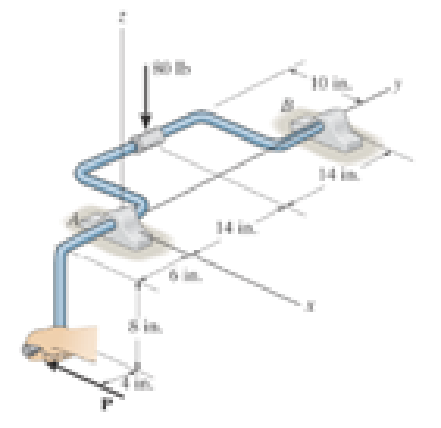
5-78. The hatch door has a weight of 80 lb and center of
gravity at G. If the force F applied to the handle at C has
coordinate direction angles of a = 60°, ß = 45°, and
y = 60°, determine the magnitude of F needed to hold the
door slightly open as shown. If the hinge at A becomes loose
from its attachment and is ineffective, what are the x, y, z
components of reaction at hinge B?
2
4 ft
3 ft.
2 ft
3 ft
C
B
X
F
Probs. 5-77/78
Chapter 5 Solutions
INTERNATIONAL EDITION---Engineering Mechanics: Statics, 14th edition (SI unit)
Ch. 5.2 - Draw the free-body diagram for the following...Ch. 5.2 - Draw the free-body diagram for the following...Ch. 5.2 - Draw the free-body diagram for the following...Ch. 5.2 - Draw the free-body diagram for the following...Ch. 5.2 - Draw the free-body diagram for the following...Ch. 5.2 - Draw the free-body diagram for the following...Ch. 5.2 - Draw the free-body diagram for the following...Ch. 5.2 - Draw the free-body diagram for the following...Ch. 5.2 - Draw the free-body diagram for the following...Ch. 5.4 - Draw the free body diagram of each object. Prob....
Ch. 5.4 - Determine the horizontal and vertical components...Ch. 5.4 - Determine the horizontal and vertical components...Ch. 5.4 - The truss is supported by a pin at A and a roller...Ch. 5.4 - Determine the components of reaction at the fixed...Ch. 5.4 - The 25 kg bar has a center of mass at G. If it is...Ch. 5.4 - Determine the reactions at the smooth contact...Ch. 5.4 - Determine the components of the support reactions...Ch. 5.4 - Determine the reactions at the supports. Prob....Ch. 5.4 - Determine the horizontal and vertical components...Ch. 5.4 - Determine the reactions at the supports. Prob....Ch. 5.4 - Determine the reactions at the supports. Prob....Ch. 5.4 - Determine the reactions at the supports. Prob....Ch. 5.4 - Determine the tension in the cable and the...Ch. 5.4 - The man attempts to a up port the toad of boards...Ch. 5.4 - Determine the components of reaction at the...Ch. 5.4 - The man has a weight W and stands at the center of...Ch. 5.4 - A uniform glass rod having a length L is placed in...Ch. 5.4 - The uniform rod AB has a mass of 40 kg. Determine...Ch. 5.4 - If the intensity of the distributed load acting on...Ch. 5.4 - If the roller at A and the pin at B can support a...Ch. 5.4 - The relay regulates voltage and current. Determine...Ch. 5.4 - Determine the reactions on the bent rod which is...Ch. 5.4 - The mobile crane is symmetrically supported by two...Ch. 5.4 - Determine the reactions acting on the smooth...Ch. 5.4 - A linear torsional spring deforms such that an...Ch. 5.4 - Determine the force P needed to pull the 50-kg...Ch. 5.4 - Determine the magnitude and direction of the...Ch. 5.4 - The operation of the fuel pump for an automobile...Ch. 5.4 - Determine the magnitude of force at the pin A and...Ch. 5.4 - The dimensions of a jib crane, which is...Ch. 5.4 - The dimensions of a jib crane, which is...Ch. 5.4 - The smooth pipe rests against the opening at the...Ch. 5.4 - The beam of negligible weight is supported...Ch. 5.4 - The cantilevered jib crane is used to support the...Ch. 5.4 - The cantilevered jib crane is used to support the...Ch. 5.4 - The bar of negligible weight is supported by two...Ch. 5.4 - Determine the stiffness k of each spring so that...Ch. 5.4 - The bulk head AD Is subjected to both water and...Ch. 5.4 - The boom supports the two vertical loads. Neglect...Ch. 5.4 - The boom is intended to support two vertical loads...Ch. 5.4 - The 10-kg uniform rod is pinned at end A. If It is...Ch. 5.4 - If the truck and its contents have a mass of 50 kg...Ch. 5.4 - Three uniform books each having a weight W and...Ch. 5.4 - Determine the reactions at the pin A and the...Ch. 5.4 - If rope BC will fail when the tension becomes 50...Ch. 5.4 - The rigid metal strip of negligible weight is used...Ch. 5.4 - The rigid metal strip of negligible weight is used...Ch. 5.4 - The cantilever footing is used to support a wail...Ch. 5.4 - The uniform beam has a weight Wand length l and is...Ch. 5.4 - A boy stands out at the end of the diving board,...Ch. 5.4 - The 30-N uniform rod has a length of l = 1 m. If s...Ch. 5.4 - The uniform rod has a length I and weight W. It is...Ch. 5.4 - I he uniform rod of length L and weight W is...Ch. 5.4 - Assuming that the foundation exerts a linearly...Ch. 5.4 - Assuming that the foundation exerts a linearly...Ch. 5.4 - If it is also subjected to a couple moment of 100...Ch. 5.4 - Determine the distance d for placement of the load...Ch. 5.4 - If d = 1 m, and = 30, determine me normal...Ch. 5.4 - The man attempts to pull the tour wheeler up the...Ch. 5.4 - Where is the best place to arrange most of the...Ch. 5.7 - Draw the free-body diagram of each object.Ch. 5.7 - In each case, write the moment equations about the...Ch. 5.7 - The uniform plate has a weight of 500 lb....Ch. 5.7 - Determine the reactions at the roller support A,...Ch. 5.7 - The rod is supported by smooth journal bearings at...Ch. 5.7 - Determine the support reactions at the smooth...Ch. 5.7 - Determine the force developed in the short link...Ch. 5.7 - Determine the components of reaction that the...Ch. 5.7 - Determine the tension each rope and the force that...Ch. 5.7 - If these components have weights WA = 45000 Wa =...Ch. 5.7 - Determine the components of reaction at the fixed...Ch. 5.7 - Determine the vertical reactions at the wheels C...Ch. 5.7 - Determine the components of reaction at A, the...Ch. 5.7 - Determine the tension in each of the three...Ch. 5.7 - Determine the components of reaction at hinges A...Ch. 5.7 - Determine me tension in each cable and the...Ch. 5.7 - The cables are attached to a smooth collar ring at...Ch. 5.7 - Determine the components of reaction at the...Ch. 5.7 - Determine the components of reaction at the...Ch. 5.7 - Determine the components of reaction at the...Ch. 5.7 - Determine the magnitude of F which will cause the...Ch. 5.7 - Determine the components of reaction at A and the...Ch. 5.7 - Determine the components of reaction at these...Ch. 5.7 - Determine the components or reaction at these...Ch. 5.7 - Compute the x, y, z components of reaction at the...Ch. 5.7 - Determine the magnitude of F2 which will cause the...Ch. 5.7 - At A the connection is with a ball-and-socket....Ch. 5.7 - If it is supported by a ball-and-socket joint at C...Ch. 5.7 - Determine the x, y, z components of reaction at...Ch. 5.7 - Determine the horizontal tension T in the belt on...Ch. 5.7 - Determine the horizontal tension T in the belt on...Ch. 5.7 - Determine the components of reaction at A and the...Ch. 5.7 - If the roller at 8 can sustain a maximum load of 3...Ch. 5.7 - Determine the reactions at the supports A and B...Ch. 5.7 - Determine the normal reaction at the roller A and...Ch. 5.7 - Determine the horizontal and vertical components...Ch. 5.7 - Determine the x, y, z components of reaction at...Ch. 5.7 - Determine the horizontal equilibrium force P that...Ch. 5.7 - Determine the x, y, z components of reaction at...Ch. 5.7 - Determine the x and z components of reaction at...
Additional Engineering Textbook Solutions
Find more solutions based on key concepts
Determine the largest load P that can be applied to the frame without causing either the average normal stress ...
Mechanics of Materials
ICA 17-24
The decay of a radioactive isotope can be theoretically modeled with the following equation, where C0...
Thinking Like an Engineer: An Active Learning Approach (4th Edition)
If x = (4t4) m, where t is in seconds, determine the magnitude of the particles velocity and acceleration when ...
Engineering Mechanics: Dynamics (14th Edition)
What parts are included in the vehicle chassis?
Automotive Technology: Principles, Diagnosis, And Service (6th Edition) (halderman Automotive Series)
1.1 Convert 1250 millimeters to meters.
Applied Fluid Mechanics (7th Edition)
The support reactions. Also, draw the free body diagrams of Joints A, B, and C of the truss.
Engineering Mechanics: Statics & Dynamics (14th Edition)
Knowledge Booster


Learn more about
Need a deep-dive on the concept behind this application? Look no further. Learn more about this topic, mechanical-engineering and related others by exploring similar questions and additional content below.Similar questions
- R5-6. A vertical force of 400 N acts on the crankshaft. Determine the horizontal equilibrium force P that must be applied to the handle and the x, y, z components of reaction at the journal bearing A and thrust bearing B. The bearings are properly aligned and exert only force reactions on the shaft. z P 400 N 150 mm 200 mm 350 mm 100 mm B 250 mm y 350 mmarrow_forwardP5-3. then draw the free-body diagrams of each member of the identify any two-force members, and frame. 800 N 200 N/m 6 m- -2 m m-arrow_forward4 of 4 5-67. Due to an unequal distribution of fuel in the wing tanks, the centers of gravity for the airplane fuselage A and wings B and C are located as shown. If these components have weights WA = 45 000 lb, WR = 8000 lb, and Wc = 6000 lb, determine the normal reactions of the wheels D, E, and F on the ground. 8 ft 4 ft 6 ft 8 ft 6 ft 20 ft 3 ftarrow_forward
- *4-20. The 1500-N electrical transformer with center of gravity at G is supported by a pin at A and a smooth pad at B. Determine the horizontal and vertical components of reaction at the pin A and the reaction of the pad B on the transformer. 0.45 m 0.9 marrow_forward4 of 5-67. Due to an unequal distribution of fuel in the wing tanks, the centers of gravity for the airplane fuselage A and wings B and C are located as shown. If these components have weights WA = 45 000 lb, Wg = 8000 lb, and Wc = 6000 lb, determine the normal reactions of the wheels D, E, and F on the ground. B. 8 ft 4 ft 6 ft 8 ft 6 ft 20 ft 3 ftarrow_forward4-37. The rod assembly is used to support the 1.25-kN cylinder. Determine the components of reaction at the ball- and-socket joint A, the smooth journal bearing E, and the force developed along rod CD. The connections at Cand D are ball-and-socket joints. 0.3 m 0.3 m 03m 0,45 marrow_forward
- *4-32. Determine the magnitude of force F that must be exerted on the handle at C to hold the 75-kg crate in the position shown. Aso, determine the components of reaction at the thrust bearing A and smooth journal bearing B. 0.1 m 0.6 m. 0.5 m 02 m 0.1 marrow_forward5-28. The hatch door has a weight of 80 lb and cente gravity at G. If the force F applied to the handle at C coordinate direction angles of a = 60°, B = 45°, y = 60°, determine the magnitude of F needed to hold door slightly open as shown. The hinges are in pr alignment and exert only force reactions on the d Determine the components of these reactions if A ex only x and z components of force and B exerts x, y, z f components. z 4 ft ---3-72 3 ft C Prob. 5-28 B X Farrow_forward5-50. The machine shown is used for forming metal plates. It consists of two toggles ABC and DEF, which are operated by the hydraulic cylinder H. The toggles push the movable bar G forward, pressing the plate p into the cavity. If the force which the plate exerts on the head is P - 12 kN, determine the force Fin the hydraulic cylinder when 8 - 30. e = 30 200 mm 00 mm P= 12 kN -F 200 mm 200 mm = 30arrow_forward
- 1 m aile Prob. 5-82 ket Inthree di 5-83. Both pulleys are fixed to the shaft and as the shaft turns with constant angular velocity, the power of pulley A is transmitted to pulley B. Determine the horizontal tension T in the belt on pulley B and the x, y, z components of t reaction at the journal bearing C and thrust bearing D if A = 0°.The bearings are in proper alignment and exert only force reactions on the shaft. determine the me each force The Theix established 200 mm 50 N 250 mm LD 300 mm -150 mm B. EGO 80 mm 65 N 80 N Prob. 5-83arrow_forwardC4-5. The tie rod is used to support this overhang at the entrance of a building. If it is pin connected to the building wall at A and to the center of the overhang B, determine if the force in the rod will increase, decrease, or remain the same if (a) the support at A is moved to a lower position D, and (b) the support at B is moved to the outer position C. Explain your answer with an equilibrium analysis, using dimensions and loads. Assume the overhang is pin supported from the building wall.arrow_forward4-5. Determine the components of the support reactions at the fixed support A on the cantilevered beam. 6 kN 1.5m 4 kN -1.5 m- -15 m-arrow_forward
arrow_back_ios
SEE MORE QUESTIONS
arrow_forward_ios
Recommended textbooks for you
 Elements Of ElectromagneticsMechanical EngineeringISBN:9780190698614Author:Sadiku, Matthew N. O.Publisher:Oxford University Press
 Mechanics of Materials (10th Edition)Mechanical EngineeringISBN:9780134319650Author:Russell C. HibbelerPublisher:PEARSON
 Thermodynamics: An Engineering ApproachMechanical EngineeringISBN:9781259822674Author:Yunus A. Cengel Dr., Michael A. BolesPublisher:McGraw-Hill Education
 Control Systems EngineeringMechanical EngineeringISBN:9781118170519Author:Norman S. NisePublisher:WILEY
 Mechanics of Materials (MindTap Course List)Mechanical EngineeringISBN:9781337093347Author:Barry J. Goodno, James M. GerePublisher:Cengage Learning
 Engineering Mechanics: StaticsMechanical EngineeringISBN:9781118807330Author:James L. Meriam, L. G. Kraige, J. N. BoltonPublisher:WILEY
Elements Of Electromagnetics
Mechanical Engineering
ISBN:9780190698614
Author:Sadiku, Matthew N. O.
Publisher:Oxford University Press
Mechanics of Materials (10th Edition)
Mechanical Engineering
ISBN:9780134319650
Author:Russell C. Hibbeler
Publisher:PEARSON
Thermodynamics: An Engineering Approach
Mechanical Engineering
ISBN:9781259822674
Author:Yunus A. Cengel Dr., Michael A. Boles
Publisher:McGraw-Hill Education
Control Systems Engineering
Mechanical Engineering
ISBN:9781118170519
Author:Norman S. Nise
Publisher:WILEY
Mechanics of Materials (MindTap Course List)
Mechanical Engineering
ISBN:9781337093347
Author:Barry J. Goodno, James M. Gere
Publisher:Cengage Learning
Engineering Mechanics: Statics
Mechanical Engineering
ISBN:9781118807330
Author:James L. Meriam, L. G. Kraige, J. N. Bolton
Publisher:WILEY
Mechanical SPRING DESIGN Strategy and Restrictions in Under 15 Minutes!; Author: Less Boring Lectures;https://www.youtube.com/watch?v=dsWQrzfQt3s;License: Standard Youtube License