
INTERNATIONAL EDITION---Engineering Mechanics: Statics, 14th edition (SI unit)
14th Edition
ISBN: 9780133918922
Author: Russell C. Hibbeler
Publisher: PEARSON
expand_more
expand_more
format_list_bulleted
Concept explainers
Videos
Textbook Question
Chapter 5.4, Problem 24P
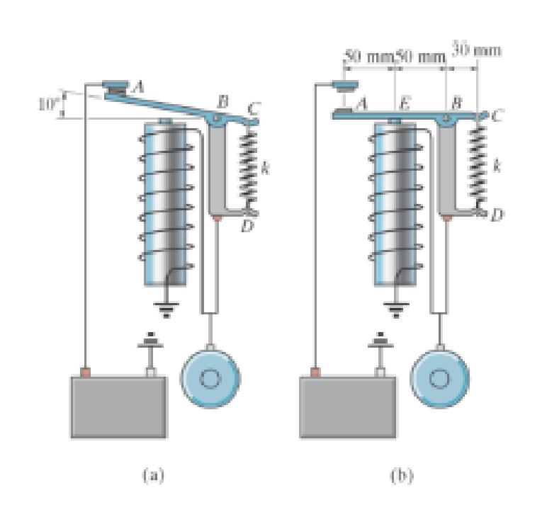
The relay regulates voltage and current. Determine the force at the spring CD, which has a stiffness or k = 120 N/m, so that it will allow the armature to make contact at A in figure (a) with a vertical force of 0.4 N. Also, determine the force in the spring when the cot is energized and attracts the armature to E, figure (b), thereby breaking contact at A.
Expert Solution & Answer
Want to see the full answer?
Check out a sample textbook solution
Students have asked these similar questions
Question 2:
The ideal spring of constant k-2.6 kN/m is attached to the disk at point A and the end fitting at point
B, as shown. The spring is unstretched when OA and Oв are both zero. If the disk is rotated 15° clockwise
and the end fitting is rotated 30°counterclockwise, determine the vector expression for the spring force
F.
Determine distance C so that the moment the spring force makes about the Z axis is equal to 10.82
N.m.
-
A = 15°1
A
250 mm
lllllll
900 mm k = 2.6 kN/m
OB = 30°
B
G
200 mm
Q4 - Two blocks A and B of weight 350 N and 600 N,
respectively are connected by a cord that passes over a
frictionless pulley, as shown in the Figure 8. Determine the
force P to be applied to block B to produce the impending
motion of block B down the plane.
Pa 0.5
50°
Pa 0.4
30°
When activated by the force P,the gripper on a robotic arm is able to pick up objects by applying the gripping force F as shown in the figure below. Given that P = 120N,calculate the gripping force F in N for the position shown.
Chapter 5 Solutions
INTERNATIONAL EDITION---Engineering Mechanics: Statics, 14th edition (SI unit)
Ch. 5.2 - Draw the free-body diagram for the following...Ch. 5.2 - Draw the free-body diagram for the following...Ch. 5.2 - Draw the free-body diagram for the following...Ch. 5.2 - Draw the free-body diagram for the following...Ch. 5.2 - Draw the free-body diagram for the following...Ch. 5.2 - Draw the free-body diagram for the following...Ch. 5.2 - Draw the free-body diagram for the following...Ch. 5.2 - Draw the free-body diagram for the following...Ch. 5.2 - Draw the free-body diagram for the following...Ch. 5.4 - Draw the free body diagram of each object. Prob....
Ch. 5.4 - Determine the horizontal and vertical components...Ch. 5.4 - Determine the horizontal and vertical components...Ch. 5.4 - The truss is supported by a pin at A and a roller...Ch. 5.4 - Determine the components of reaction at the fixed...Ch. 5.4 - The 25 kg bar has a center of mass at G. If it is...Ch. 5.4 - Determine the reactions at the smooth contact...Ch. 5.4 - Determine the components of the support reactions...Ch. 5.4 - Determine the reactions at the supports. Prob....Ch. 5.4 - Determine the horizontal and vertical components...Ch. 5.4 - Determine the reactions at the supports. Prob....Ch. 5.4 - Determine the reactions at the supports. Prob....Ch. 5.4 - Determine the reactions at the supports. Prob....Ch. 5.4 - Determine the tension in the cable and the...Ch. 5.4 - The man attempts to a up port the toad of boards...Ch. 5.4 - Determine the components of reaction at the...Ch. 5.4 - The man has a weight W and stands at the center of...Ch. 5.4 - A uniform glass rod having a length L is placed in...Ch. 5.4 - The uniform rod AB has a mass of 40 kg. Determine...Ch. 5.4 - If the intensity of the distributed load acting on...Ch. 5.4 - If the roller at A and the pin at B can support a...Ch. 5.4 - The relay regulates voltage and current. Determine...Ch. 5.4 - Determine the reactions on the bent rod which is...Ch. 5.4 - The mobile crane is symmetrically supported by two...Ch. 5.4 - Determine the reactions acting on the smooth...Ch. 5.4 - A linear torsional spring deforms such that an...Ch. 5.4 - Determine the force P needed to pull the 50-kg...Ch. 5.4 - Determine the magnitude and direction of the...Ch. 5.4 - The operation of the fuel pump for an automobile...Ch. 5.4 - Determine the magnitude of force at the pin A and...Ch. 5.4 - The dimensions of a jib crane, which is...Ch. 5.4 - The dimensions of a jib crane, which is...Ch. 5.4 - The smooth pipe rests against the opening at the...Ch. 5.4 - The beam of negligible weight is supported...Ch. 5.4 - The cantilevered jib crane is used to support the...Ch. 5.4 - The cantilevered jib crane is used to support the...Ch. 5.4 - The bar of negligible weight is supported by two...Ch. 5.4 - Determine the stiffness k of each spring so that...Ch. 5.4 - The bulk head AD Is subjected to both water and...Ch. 5.4 - The boom supports the two vertical loads. Neglect...Ch. 5.4 - The boom is intended to support two vertical loads...Ch. 5.4 - The 10-kg uniform rod is pinned at end A. If It is...Ch. 5.4 - If the truck and its contents have a mass of 50 kg...Ch. 5.4 - Three uniform books each having a weight W and...Ch. 5.4 - Determine the reactions at the pin A and the...Ch. 5.4 - If rope BC will fail when the tension becomes 50...Ch. 5.4 - The rigid metal strip of negligible weight is used...Ch. 5.4 - The rigid metal strip of negligible weight is used...Ch. 5.4 - The cantilever footing is used to support a wail...Ch. 5.4 - The uniform beam has a weight Wand length l and is...Ch. 5.4 - A boy stands out at the end of the diving board,...Ch. 5.4 - The 30-N uniform rod has a length of l = 1 m. If s...Ch. 5.4 - The uniform rod has a length I and weight W. It is...Ch. 5.4 - I he uniform rod of length L and weight W is...Ch. 5.4 - Assuming that the foundation exerts a linearly...Ch. 5.4 - Assuming that the foundation exerts a linearly...Ch. 5.4 - If it is also subjected to a couple moment of 100...Ch. 5.4 - Determine the distance d for placement of the load...Ch. 5.4 - If d = 1 m, and = 30, determine me normal...Ch. 5.4 - The man attempts to pull the tour wheeler up the...Ch. 5.4 - Where is the best place to arrange most of the...Ch. 5.7 - Draw the free-body diagram of each object.Ch. 5.7 - In each case, write the moment equations about the...Ch. 5.7 - The uniform plate has a weight of 500 lb....Ch. 5.7 - Determine the reactions at the roller support A,...Ch. 5.7 - The rod is supported by smooth journal bearings at...Ch. 5.7 - Determine the support reactions at the smooth...Ch. 5.7 - Determine the force developed in the short link...Ch. 5.7 - Determine the components of reaction that the...Ch. 5.7 - Determine the tension each rope and the force that...Ch. 5.7 - If these components have weights WA = 45000 Wa =...Ch. 5.7 - Determine the components of reaction at the fixed...Ch. 5.7 - Determine the vertical reactions at the wheels C...Ch. 5.7 - Determine the components of reaction at A, the...Ch. 5.7 - Determine the tension in each of the three...Ch. 5.7 - Determine the components of reaction at hinges A...Ch. 5.7 - Determine me tension in each cable and the...Ch. 5.7 - The cables are attached to a smooth collar ring at...Ch. 5.7 - Determine the components of reaction at the...Ch. 5.7 - Determine the components of reaction at the...Ch. 5.7 - Determine the components of reaction at the...Ch. 5.7 - Determine the magnitude of F which will cause the...Ch. 5.7 - Determine the components of reaction at A and the...Ch. 5.7 - Determine the components of reaction at these...Ch. 5.7 - Determine the components or reaction at these...Ch. 5.7 - Compute the x, y, z components of reaction at the...Ch. 5.7 - Determine the magnitude of F2 which will cause the...Ch. 5.7 - At A the connection is with a ball-and-socket....Ch. 5.7 - If it is supported by a ball-and-socket joint at C...Ch. 5.7 - Determine the x, y, z components of reaction at...Ch. 5.7 - Determine the horizontal tension T in the belt on...Ch. 5.7 - Determine the horizontal tension T in the belt on...Ch. 5.7 - Determine the components of reaction at A and the...Ch. 5.7 - If the roller at 8 can sustain a maximum load of 3...Ch. 5.7 - Determine the reactions at the supports A and B...Ch. 5.7 - Determine the normal reaction at the roller A and...Ch. 5.7 - Determine the horizontal and vertical components...Ch. 5.7 - Determine the x, y, z components of reaction at...Ch. 5.7 - Determine the horizontal equilibrium force P that...Ch. 5.7 - Determine the x, y, z components of reaction at...Ch. 5.7 - Determine the x and z components of reaction at...
Knowledge Booster


Learn more about
Need a deep-dive on the concept behind this application? Look no further. Learn more about this topic, mechanical-engineering and related others by exploring similar questions and additional content below.Similar questions
- There are two parallel forces and two pure moments in the figure. What distance "d" must separate the forces in order for the system to be in equilibrium? F = 9 N, M1 = 15 N-m, M2 = 69 N-m, = 60 degrees, a = 1 m, b = 1 m, c = 2 marrow_forward2: This fuel pump uses the reciprocating action of rocker arm ABC. The arm is pinned at B and is spring loaded at A and D. Calculate the forces acting at pin B and in the spring at point D. FA=60 N A 50 mm 10 mm D Fe= 125 N -20 mmarrow_forwardThe figure shows a control bar, subjected to a force of 90N. Since the length of the bar is 225 mm and the moment of the clockwise force on B is 13.5 N.m, determine the value of α. Solve the problem using scalar notation and explain your result.arrow_forward
- Draw a free-body diagram for this system.arrow_forwardUse the method of members to find the components of the forces acting on the frame with P=750N and Q=3000Narrow_forwardThe operation of the fuel pump for an automobile depends on the reciprocating action of the rocker arm ABC, which is pinned at B and is spring loaded at A and D. The smooth cam C is in the position shown. The vertical force acting on the rocker arm at A is F = 80 N, and at C it is Fc = 115 N. (Figure 1) Figure 10 m 1 of 1 > 20 mm- Part A Determine the z and y components of the reaction force on the rocker arm ABC at the pin for equilibrium. Express your answers using three significant figures separated by a comma. B. By Submit Part B Az it vec Bequest Answer FD- Value Determine the magnitude of the force along the spring DF for equilibrium, Express your answer to three significant figures and include the appropriate units. Submit Request Answer Units ? ? Narrow_forward
- An eye bolt is used to attach 3 cables to a steel plate. The tension in the three cables create F1=200 lbf, F2=250 lbf, and F3=100 lbf with 0 = 30 degrees and p=24.1 degrees. If the eye bolt is in equilibrium, what is the x-component of the sum of other forces on the bolt (force from the nut and plate on the bolt) ? If you add up the three force vectors, the sum other force you are looking for will just be in the opposite direction to put the eye bolt in equilibrium. The x-direction is positive to the right. For example, if you find the sum of forces 1, 2, and 3 are 100 Ibf to the right, then the other forces in the x-direction must be pointing to the left (-100 lbf) to put the eye bolt in equilibrium. Eye bolt 2steel 3 plate Nut t Wonsherarrow_forwardWhen activated by the force P, the gripper on a robotic arm is able to pick up objects by applying the gripping force F as shown in the figure below. Given that P = 120 N, calculate the gripping force F in N for the position shown.arrow_forward5) In the figure shown below the person pulls the cable vertically downward to move box number 1, find the amount of tension in the cable at the start of the motion, assuming W1=W2= 500 N, p1=0.3 and p2=0.6.arrow_forward
- The spring ABC has a stiffness of 500N/m and an unstretched length of 6m. Calculate the horizontal force, F applied to the cord which is attached at B so that the displacement of the pulley from the wall is d= 1.5m. A k = 500 N/m 6 m F k = 500 N/m Fig. Q3 Force equation: Force equation 3D Moment 3D Cosine rule R - 4 +B-2AB cos e F- Fi+Fj+Fk Ff = F +F +F moment about a point M-rxF Sine rule F| di+dj+dk F F3 Fc sin 4 sin B sinC moment about an axis M=rF Force resultant R-R R +R R. 8= tan Rarrow_forward2 m 3 m 0.75 m 30° 1m 60° y F The system shown is supported by journal bearings at points A, B, and C. The applied force F has a magnitude of 1000N. Take the following support reactions: •Cx=-100 N (acting in negative x-direction) Cy = -1000 N (acting in negative y-direction) • By = +750 N (acting in positive y-direction) Which of the following is closest to the magnitude of the force reaction at A in the z- direction (i.e. Az)? 身arrow_forwardThe forces acting on the arm of an athlete doing shoulder exercises are shown in the figure. The athlete holds his arm at an angle of β=15° with the horizontal axis. Point O represents the axis of rotation in the shoulder joint, point A represents the connection point of the deltoid muscle to the humerus, point B represents the center of gravity of the arm, and point C represents the application point of the force acting on the hand. The distances between the rotation axis (O point) of the shoulder joint and the points A, B and C are a=20 cm, b =33 cm and c= 65 cm, respectively. The athlete's hand is exerted by a force of F= 150 N, which makes an angle of γ=30° with the vertical from the point C. The weight of the athlete's arm is W= 100 N. The direction of application of the Fm muscle force makes an angle of α=25° with the longitudinal axis of the arm. According to this; a) Calculate the FM muscle strength. b) Calculate the angle θ of the FJ joint reaction force with the horizontal.…arrow_forward
arrow_back_ios
SEE MORE QUESTIONS
arrow_forward_ios
Recommended textbooks for you
 Elements Of ElectromagneticsMechanical EngineeringISBN:9780190698614Author:Sadiku, Matthew N. O.Publisher:Oxford University Press
 Mechanics of Materials (10th Edition)Mechanical EngineeringISBN:9780134319650Author:Russell C. HibbelerPublisher:PEARSON
 Thermodynamics: An Engineering ApproachMechanical EngineeringISBN:9781259822674Author:Yunus A. Cengel Dr., Michael A. BolesPublisher:McGraw-Hill Education
 Control Systems EngineeringMechanical EngineeringISBN:9781118170519Author:Norman S. NisePublisher:WILEY
 Mechanics of Materials (MindTap Course List)Mechanical EngineeringISBN:9781337093347Author:Barry J. Goodno, James M. GerePublisher:Cengage Learning
 Engineering Mechanics: StaticsMechanical EngineeringISBN:9781118807330Author:James L. Meriam, L. G. Kraige, J. N. BoltonPublisher:WILEY
Elements Of Electromagnetics
Mechanical Engineering
ISBN:9780190698614
Author:Sadiku, Matthew N. O.
Publisher:Oxford University Press
Mechanics of Materials (10th Edition)
Mechanical Engineering
ISBN:9780134319650
Author:Russell C. Hibbeler
Publisher:PEARSON
Thermodynamics: An Engineering Approach
Mechanical Engineering
ISBN:9781259822674
Author:Yunus A. Cengel Dr., Michael A. Boles
Publisher:McGraw-Hill Education
Control Systems Engineering
Mechanical Engineering
ISBN:9781118170519
Author:Norman S. Nise
Publisher:WILEY
Mechanics of Materials (MindTap Course List)
Mechanical Engineering
ISBN:9781337093347
Author:Barry J. Goodno, James M. Gere
Publisher:Cengage Learning
Engineering Mechanics: Statics
Mechanical Engineering
ISBN:9781118807330
Author:James L. Meriam, L. G. Kraige, J. N. Bolton
Publisher:WILEY
Column buckling; Author: Amber Book;https://www.youtube.com/watch?v=AvvaCi_Nn94;License: Standard Youtube License