Shigley's Mechanical Engineering Design (McGraw-Hill Series in Mechanical Engineering)
10th Edition
ISBN: 9780073398204
Author: Richard G Budynas, Keith J Nisbett
Publisher: McGraw-Hill Education
bartleby

Concept explainers

bartleby

Videos

Question
Book Icon
Chapter 5, Problem 75P
To determine

The factor of safety using distortion energy theory.

Expert Solution & Answer
Check Mark

Answer to Problem 75P

The factor of safety using distortion energy theory for inner radius is 1.92.

The factor of safety using distortion energy theory for outer radius is 1.95.

Explanation of Solution

Write the expression for contact pressure.

    p=(Eδd2d3)[(do2d2)(d2di2)(do2di2)]                                                      (I)

Here, the contact pressure is p, the Yong’s modulus is E, the diametral interference is δd, the inner diameter is di, the outer diameter is do and the nominal diameter is d.

Write the expression for inner radius.

    ri=di2                                                                                                 (II)

Here, the inner radius is ri.

Write the expression for outer radius.

    ro=do2                                                                                               (III)

Here, the outer radius is ro.

Write the expression for tangential stress at outer radius for inner member.

    (σt)o=[ro2+ri2ro2ri2](P)                                                                    (IV)

Here, the tangential stress at outer radius for inner member is (σt)o.

Write the expression for tangential stress at inner radius for inner member.

    (σt)i=(2ro2ro2ri2)(p)                                                                      (V)

Here, the tangential stress for inner member is (σt)i.

Write the expression for radial stress at outer radius for inner member.

    (σr)o=p                                                                                       (VI)

Here, the radial stress for inner member is (σr)o.

Write the expression for second moment of area.

    I=(π64)(d4di4)                                                                           (VII)

Here, the second moment of area is I.

Write the expression for stress.

    (σx)=±(McI)                                                                             (VIII)

Here, the stress in x plane is (σx), the bending-moment is M, the distance of the member from neutral axis is c.

Write the expression for second polar moment of area.

    J=2I                                                                                             (IX)

Here, the second polar moment of area is J.

Write the expression for shear stress.

    (τxy)=(TcJ)                                                                                       (X)

Here, the shear stress is τxy, the torque is T.

Write the expression for von Mises stress for inner radius.

    σi=(σx2σxσy+σy2+3τxy2)12                                                           (XI)

Here, the von Mises stress is σi, the stress in y plane is σy and shear stress in xy plane is τxy

Calculate factor of safety for inner radius.

    ni=(Syσi)                                                                                        (XII)

Here, the factor of safety for outer radius is ni and the yield strength is Sy.

Write the expression for von Mises stress for outer radius.

    σo=(12)[(σxσy)2+(σyσz)2+(σzσx)2+6(τxy)2]12         (XIII)

Here, the von Mises stress for inner radius is σo and stress in z plane is σz.

Calculate the factor of safety for outer radius.

    no=(Syσo)                                                                                       (XIV)

Here, the factor of safety for outer radius is no.

Write the expression for nominal radius.

    r=d2                                                                                               (XV)

Here, the nominal radius is r.

Conclusion:

Substitute 207GPa for E, 0.062mm for δd, 50mm for do, 45mm for d and 40mm for di in Equation (I).

    p=((207GPa)(0.062mm)2(45mm)3)[((50mm)2(45mm)2)((45mm)2(40mm)2)((50mm)2(40mm)2)]=(207GPa)(103MPa1GPa)(7.63069×10⁵)=15.7955MPa15.8MPa

Substitute 40mm for di in Equation (II).

    ri=di2=40mm2

Substitute 45mm for do in Equation (III).

    ro=do2=45mm2

Substitute 50mm for d in Equation (XV).

    r=d2=50mm2

Substitute (40mm2) for ri, 15.8MPa for p, (45mm2) for ro in Equation (IV).

    (σt)o=[(45mm2)2+(40mm2)2(45mm2)2(40mm2)2](15.8MPa)=(8.529)(15.8MPa)134.7MPa

The radial stress for inner radius is zero at inner member.

    (σr)i=0

Substitute (45mm2) for ro, (40mm2) for ri, and 15.8MPa for p in Equation (V).

    (σt)i=(2(45mm2)2(45mm2)2(40mm2)2)(15.8MPa)=(9.5294)(15.8MPa)150.6MPa

Substitute 15.8MPa for p in Equation (VI).

    (σr)o=15.8MPa

Substitute 50mm for d and 40mm for di in Equation (VII).

    I=(π64)((50mm)4(40mm)4)=(π64)(3690000mm4)=(181132.4514)mm4(181.132×10³)mm4

Substitute (ro) for c, for outer member in Equation (VIII).

    (σx)o=±(M(ro)I)                                                                    (XVI)

Here, the stress in outer member is (σx)o.

Substitute 675Nm for M, (45mm2) for ro and (181.132×10³)mm4 for I in Equation (XVI).

    (σx)o=±((675Nm)(45mm2)(181.132×10³)mm4)=±((675Nm)(22.5mm)(1m1000mm)(181.132×10³)mm4(1012m41mm4))=±(83.847×10⁶)N/m2(1MPa106N/m2)±(83.9)MPa

Substitute (r) for c, for inner member in Equation (VIII).

    (σx)i=±(M(r)I)                                                                       (XVII)

Here, the stress for inner member is (σx)i.

Substitute 675Nm for M, (40mm2) for r and (181.132×10³)mm4 for I in Equation (XVII).

    (σx)i=±((675Nm)(40mm2)(181.132×10³)mm4)=±((675Nm)(20mm)(1m1000mm)(181.132×10³)mm4(1012m41mm4))=±(74.531×10⁶)N/m2(1MPa106N/m2)±(74.5)MPa

Substitute (181.132×10³)mm4 for I in Equation (IX).

    J=2I=(362.26×10³)mm4

Substitute ro for c, for outer member in Equation (X).

    (τxy)o=(T(ro)J)                                                                       (XVIII)

Here, the shear stress for outer member is (τxy)o.

Substitute 900Nm for T, (45mm2) for ro and (362.26×10³)mm4 for J in Equation (XVIII).

    (τxy)o=((900Nm)(45mm2)(362.26×10³)mm4)=((900Nm)(45mm2)(1m1000mm)(362.26×10³)mm4(1012m41mm4))=(55.899×10⁶)N/m2(1MPa106N/m2)55.9MPa

Substitute r for c, for outer member in Equation (X).

    (τxy)i=(T(r)J)                                                                          (XIX)

Here, the shear stress for inner member is (τxy)i.

Substitute 900Nm for T, (40mm2) for ro and (362.26×10³)mm4 for J in Equation (XIX).

    (τxy)i=((900Nm)(40mm2)(362.26×10³)mm4)=((900Nm)(40mm2)(1m1000mm)(362.26×10³)mm4(1012m41mm4))=(49.688×10⁶)N/m2(1MPa106N/m2)49.7MPa

Substitute 74.5MPa for σx, 150.6MPa for σy and 49.7MPa for τxy in Equation (XI).

    σi=[((74.5MPa)2((74.5MPa)(150MPa))+(150.6MPa)2+3(49.7MPa)2)]12=[(46815.88MPa2)]12216.37MPa

Substitute 415MPa for Sy and 216.37MPa for σi in Equation (XII).

    ni=(415MPa216.37MPa)=1.918011.92

Thus, the factor of safety for outer radius is 1.92.

The following diagram shows the 3D stress for outer radius.
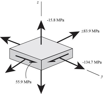
Shigley's Mechanical Engineering Design (McGraw-Hill Series in Mechanical Engineering), Chapter 5, Problem 75P

Figure (1)

Substitute (+83.9MPa) for σx, 134.7MPa for σy, (15.8MPa) for σz and 55.9MPa for τxy in Equation (XII).

    σo=(12)[((83.9MPa)(134.7MPa))2+((134.7MPa)(15.8MPa))2+((15.8MPa)(83.9MPa))2+6((55.9MPa)2)]12=(12)[(90612.12MPa)]12=212.8522MPa212.85MPa

Substitute (83.9MPa) for σx, 134.7MPa for σy, (15.8MPa) for σz and 55.9MPa for τxy in Equation (XIII).

    σo=(12)[((83.9MPa)(134.7MPa))2+((134.7MPa)(15.8MPa))2+((15.8MPa)(83.9MPa))2+6((55.9MPa)2)]12=(12)[(40104.32MPa)]12=141.6056MPa141.6MPa

The value of σo is larger for the positive value of σx. Thus, the value of σo is used as 212.85MPa to calculate the factor of safety.

Substitute 415MPa for Sy and 212.85MPa for σ in Equation (XIV).

    no=(415MPa212.85MPa)=1.9491.95

Thus, the factor of safety for outer radius is 1.95.

Want to see more full solutions like this?

Subscribe now to access step-by-step solutions to millions of textbook problems written by subject matter experts!
Students have asked these similar questions
The connection between an electric motor and a construction machine shaft is provided by means of a rigid coupling with flanges, through which the moment is transferred via the coupling flanges.The power of the electric motor is 35kw and the speed is 870rpm. The coupling flanges are connected with three bolts of quality 5.6 with a placement diameter of 40 mm.The surface pressure safety stress for bolts is 16 MPa. The contact length of the bolt with the coupling flange is 12 mm. The coefficient of friction on the flange surfaces is 0.14; the operating factor for the coupling is 0.8. The working conditions of the contact element, the material properties are very well known; since force and stress analyses can be performed with high accuracy,; question) Determine the bolt that should be used in the clutch from the table.
An A-992 steel wire is connected at ends B and C With an initial diameter of 15 mm. The weight of bar AB is negligible along with any friction in the pins. The area contraction of wire BC cannot exceed 0.0030%. As shown in the figure, What is the mass of the heaviest possible uniform cylinder supported as shown in the figure? 6 m- B
5-126* A short standard-weight steel pipe (see Appendix B) is used to support an axial compressive load of 100 kN. If yield- ing (o, = 250 MPa) should not occur and the factor of safety is to be 1.6, determine the smallest nominal diameter pipe that may be used to support the load.

Chapter 5 Solutions

Shigley's Mechanical Engineering Design (McGraw-Hill Series in Mechanical Engineering)

Ch. 5 - 5-7 to 5-11 An AISI 1018 steel has a yield...Ch. 5 - A ductile material has the properties Syt = 60...Ch. 5 - Prob. 13PCh. 5 - Prob. 14PCh. 5 - Prob. 15PCh. 5 - 5-14 to 5-18 An AISI 4142 steel QT at 800F...Ch. 5 - 5-14 to 5-18 An AISI 4142 steel QT at 800F...Ch. 5 - 5-14 to 5-18 An AISI 4142 steel QT at 800F...Ch. 5 - A brittle material has the properties Sut = 30...Ch. 5 - Repeat Prob. 519 by first plotting the failure...Ch. 5 - For an ASTM 30 cast iron, (a) find the factors of...Ch. 5 - For an ASTM 30 cast iron, (a) find the factors of...Ch. 5 - Prob. 23PCh. 5 - For an ASTM 30 cast iron, (a) find the factors of...Ch. 5 - 5-21 to 5-25 For an ASTM 30 cast iron, (a) find...Ch. 5 - 5-26 to 5-30 A cast aluminum 195-T6 exhibits Sut =...Ch. 5 - 5-26 to 5-30 A cast aluminum 195-T6 exhibits Sut =...Ch. 5 - 5-26 to 5-30 A cast aluminum 195-T6 exhibits Sut =...Ch. 5 - 5-26 to 5-30 A cast aluminum 195-T6 exhibits Sut =...Ch. 5 - 5-26 to 5-30 A cast aluminum 195-T6 exhibits Sut =...Ch. 5 - 5-31 to 5-35 Repeat Probs. 526 to 530 using the...Ch. 5 - 5-31 to 5-35 Repeat Probs. 526 to 530 using the...Ch. 5 - Repeat Probs. 526 to 530 using the modified-Mohr...Ch. 5 - Repeat Probs. 526 to 530 using the modified-Mohr...Ch. 5 - Repeat Probs. 526 to 530 using the modified-Mohr...Ch. 5 - This problem illustrates that the factor of safety...Ch. 5 - For the beam in Prob. 344, p. 147, determine the...Ch. 5 - A 1020 CD steel shaft is to transmit 20 hp while...Ch. 5 - For the problem specified in the table, build upon...Ch. 5 - For the problem specified in the table, build upon...Ch. 5 - 5-39 to 5-55 For the problem specified in the...Ch. 5 - Prob. 42PCh. 5 - For the problem specified in the table, build upon...Ch. 5 - For the problem specified in the table, build upon...Ch. 5 - Prob. 45PCh. 5 - 5-39 to 5-55 For the problem specified in the...Ch. 5 - Prob. 47PCh. 5 - For the problem specified in the table, build upon...Ch. 5 - For the problem specified in the table, build upon...Ch. 5 - For the problem specified in the table, build upon...Ch. 5 - For the problem specified in the table, build upon...Ch. 5 - 5-39 to 5-55 For the problem specified in the...Ch. 5 - 5-39 to 5-55 For the problem specified in the...Ch. 5 - For the problem specified in the table, build upon...Ch. 5 - For the problem specified in the table, build upon...Ch. 5 - Build upon the results of Probs. 384 and 387 to...Ch. 5 - Using F = 416 lbf, design the lever arm CD of Fig....Ch. 5 - A spherical pressure vessel is formed of 16-gauge...Ch. 5 - This problem illustrates that the strength of a...Ch. 5 - Prob. 60PCh. 5 - A cold-drawn AISI 1015 steel tube is 300 mm OD by...Ch. 5 - Prob. 62PCh. 5 - The figure shows a shaft mounted in bearings at A...Ch. 5 - By modern standards, the shaft design of Prob. 563...Ch. 5 - Build upon the results of Prob. 340, p. 146, to...Ch. 5 - For the clevis pin of Prob. 340, p. 146, redesign...Ch. 5 - A split-ring clamp-type shaft collar is shown in...Ch. 5 - Prob. 68PCh. 5 - Prob. 69PCh. 5 - Prob. 70PCh. 5 - Two steel tubes have the specifications: Inner...Ch. 5 - Repeal Prob. 5-71 for maximum shrink-fit...Ch. 5 - Prob. 73PCh. 5 - Two steel lubes are shrink-filled together where...Ch. 5 - Prob. 75PCh. 5 - Prob. 76PCh. 5 - Prob. 77PCh. 5 - Prob. 78PCh. 5 - Prob. 79PCh. 5 - Prob. 80PCh. 5 - Prob. 81PCh. 5 - For Eqs. (5-36) show that the principal stresses...Ch. 5 - Prob. 83PCh. 5 - A plate 100 mm wide, 200 mm long, and 12 mm thick...Ch. 5 - A cylinder subjected to internal pressure pi has...
Knowledge Booster
Background pattern image
Mechanical Engineering
Learn more about
Need a deep-dive on the concept behind this application? Look no further. Learn more about this topic, mechanical-engineering and related others by exploring similar questions and additional content below.
Similar questions
SEE MORE QUESTIONS
Recommended textbooks for you
Text book image
Mechanics of Materials (MindTap Course List)
Mechanical Engineering
ISBN:9781337093347
Author:Barry J. Goodno, James M. Gere
Publisher:Cengage Learning
Stresses Due to Fluctuating Loads Introduction - Design Against Fluctuating Loads - Machine Design 1; Author: Ekeeda;https://www.youtube.com/watch?v=3FBmQXfP_eE;License: Standard Youtube License