
Concept explainers
Videos
For the problem specified in the table, build upon the results of the original problem to determine the minimum factor of safety for yielding. Use both the maximum-shear-stress theory and the distortion-energy theory, and compare the results. The material is 1018 CD steel.


3–72* to 3–73*
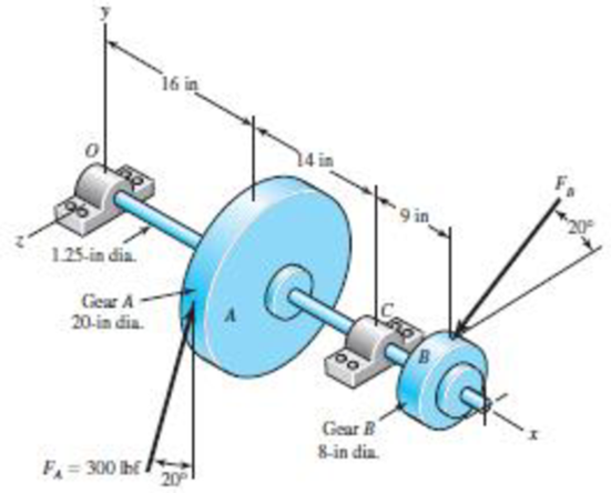
A gear reduction unit uses the countershaft shown in the figure. Gear A receives power from another gear with the transmitted force FA applied at the 20° pressure angle as shown. The power is transmitted through the shaft and delivered through gear B through a transmitted force FB at the pressure angle shown.
(a) Determine the force FB, assuming the shaft is running at a constant speed.
(b) Find the bearing reaction forces, assuming the bearings act as simple supports.
(c) Draw shear-force and bending-moment diagrams for the shaft. If needed, make one set for the horizontal plane and another set for the vertical plane.
(d) At the point of maximum bending moment, determine the bending stress and the torsional shear stress.
(e) At the point of maximum bending moment, determine the principal stresses and the maximum shear stress.
The factor of safety for yielding from distortion-energy theory.
The factor of safety for yielding from maximum-shear-stress theory.
Answer to Problem 43P
The factor of safety for yielding from distortion-energy theory is
The factor of safety for yielding from maximum-shear-stress theory is
Explanation of Solution
The figure below shows the free body diagram of pulley A.
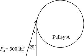
Figure (1)
The figure below shows the free body diagram of pulley B.
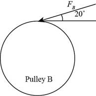
Figure (2)
Calculate the force
Here, the force acting on pulley
Write the moment about bearing
Here, the reaction force at bearing
Write the equation to balance the forces in
Here, the reaction force at bearing
Write the moment about bearing
Here, the reaction force at bearing
Write the equation to balance the forces in
Here, the reaction force at bearing
Calculate the reaction forces at bearing
Here, the reaction force at bearing
Calculate the reaction forces at bearing
Here, the reaction force at bearing
The calculations for shear force and bending moment diagram in
Calculate the shear force at
Here, the shear force at
Calculate the shear force at
Here, the shear force at
Calculate the shear force at
Here, the shear force at
Calculate the shear force at
Here, the shear force at
Calculate the moment at
Here, the moment at
Calculate the moment at
Here, the moment at
Calculate the moment at
Here, the moment at
Write the net moment at
Here, the net moment at
Write the net moment at
Here, the net moment at
Write the torque transmitted by shaft from
Here, the torque transmitted by shaft from
Calculate the bending stress.
Here, the bending stress is
Calculate the shear stress.
Here, the shear stress is
Calculate the maximum principal stress.
Here, the maximum principal stress is
Calculate the minimum principal stress.
Here, the minimum principal stress is
Calculate the maximum shear stress.
Here, maximum shear stress is
Calculate the factor of safety from maximum-shear-stress theory.
Here, the maximum yield stress for
Calculate the factor of safety from distortion-energy theory.
Here, the Von Mises stress is
Write the expression for von Mises stress.
Substitute
Conclusion:
Substitute
Thus, the force
Substitute
Substitute
Substitute
Substitute
Substitute
Substitute
Substitute
Substitute
Substitute
Substitute
Substitute
Substitute
The shear force and bending moment diagram in
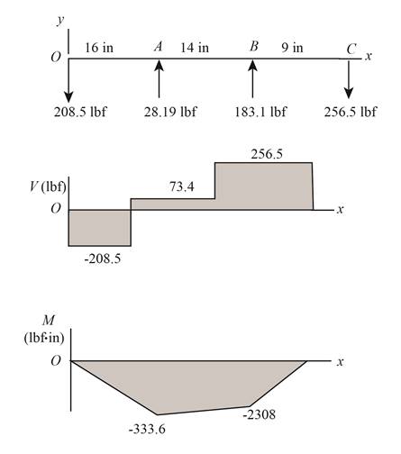
Figure-(3)
Substitute
Substitute
Substitute
Substitute
Substitute
Substitute
Thus, the shear force and bending moment diagram in
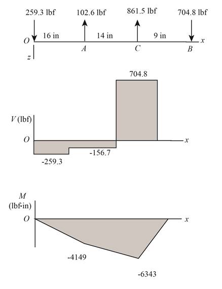
Figure-(4)
Substitute
Substitute
Since,
Substitute
Substitute
Thus, the bending stress at point of maximum bending moment is
Substitute
Substitute
Substitute
Substitute
Refer to the Table A-20 “Deterministic ASTM Minimum Tensile and Yield Strengths for Some Hot-Rolled (HR) and Cold-Drawn (CD) Steels” and obtain the yield strength as
Substitute
Thus, the factor of safety for yielding from maximum-shear-stress theory is
Substitute
Thus, the factor of safety for yielding from distortion-energy theory is
Want to see more full solutions like this?
Chapter 5 Solutions
Shigley's Mechanical Engineering Design (McGraw-Hill Series in Mechanical Engineering)


- Topic: FUNDAMENTAL CONCEPT OF STRAIN (statically indeterminate) and TORSION (circular shafts and thin-walled tubes). Problem: A shaft with a constant diameter of 2” is loaded by torques applied to gears attached to it as shown. Using G = 12 x 106 psi, determine the relative angle of twist (in degree) of gear A relative to gear D. Use 2 decimal places. Use the given sign convention for uniformity. Provide a torque diagramarrow_forwardAn input shaft of a gearbox with motor power P = 7 kW and rotation number n = 1300 rpm. The diameter of an input shaft is d = 20 mm and its material is 16MnCr5. A force of F = 2800 N forces the shaft due to the operation of a gear wheel connected with a wedge on the input shaft. The distances of the gear from the bearings are given as L₁ = 40 mm and L2 = 60 mm. In the most dangerous section, you are required to check the strength according to the S = 3 safety factor. If the section is unsafe in terms of strength, what changes would you make in the design to make it safe? (The surface of the spindle is machined as fine chips, reliability poor Kg = 1.).arrow_forwardASAParrow_forward
- L length of the adjustable wrench in the figure; Choose a number from 152 to 252 mm that does not end with a zero. F force also; Choose from 122 to 292 N as a non-zero number. Find the torque and direction of the wrench applied to the bolt. ?arrow_forwardIn the fabric dye-printing system given in the figure, the motion is transmitted from the electric motor to the drum of the machine. There is a two-stage reducer in between. Number of teeth of gears z1=17; z2=85; z3=18; z4=72; The efficiency of a pair of gears is given as na=0.97 and the efficiency of each of the gearbox shafts and lower bearing pairs to the drum bearing is given as n=0.97. The diameter of the drum will be D=200 mm, the fabric speed will be v=1 m/s and the pulling force required to activate the band will be taken as F-2000 N. a) Find the number of revolutions of the engine. b) Find the required engine power.arrow_forwardGear shaft ABCDE is subjected to the torques shown in the figure. Find the internal torque in each seg- ment, and then plot the torsional moment diagram. Assume that the spacing between gears is constant, i.e., 10 in. T1 = T2 = 1000 lb-in. 500 lb-in. A B T3 = 800 Ib-in. C Ta = 500 lb-in. d = 1.0 in. D T; = 800 lb-in. Earrow_forward
- 427 12T 4 30T In the gear train shown in sketch c the pinion rotates at 520 rpm and transfers 6.9 kW to the train. The circular pitch is 38.25 mm and the pressure angle is 18.5º. Find: 1. the output speed. 2. Draw a free-body diagram of the forces acting on each gear. 3. Find the reaction forces at shaft of the gear 4.arrow_forwardThe shaft shown in the figure is machined from AISI 1040 CD steel. The shaft rotates at 1600 rpm and is supported in rolling bearings at A and B. The applied forces are F1 = 1600 lbf and F2 = 640 lbf. A steady torque of 1600 lbf·in is being transmitted through the shaft between the points of application of the forces.arrow_forward2- A chain drive using bush roller chain transmits 5500 W of power. The driving shaft on an electric motor runs at 1440 r.p.m. and velocity ratio is 4.6:1. The drive is required to operate continuously with periodic lubrication and driven machine is such that load can be regarded as fairly constant. Considering the center distance to be as minimum as possible, design the chain drive by calculating leading dimensions, number of teeth and length of the chain.arrow_forward
- The figure (attached) shows a belt pulley mechanism which is loaded statically. The shaft is made of AISI 1030 steel with the yield strength of 480 MPa. Using distortion energy theory (DET), determine the diameter of the shaft with a factor of safety of 2.arrow_forwardA power transmission mechanism consists of a belt drive and a gear train as shown in the figure. Diameters of pulleys of belt drive and number of teeth (T) on the gears 2 to 7 are indicated in the figure. Find the speed and direction of rotation of gear 7 ? !187 2 N = 2500 rpm 150 mm 250 mm 36T 157 167 337 44Tarrow_forwardThe shaft shown in the figure is machined from AISI 1040 CD steel. The shaft rotates at 1600 rpm and is supported in rolling bearings at A and B. The applied forces are F₁ = 1600 lbf and F2 = 640 lbf. A steady torque of 1600 lbf-in is being transmitted through the shaft between the points of application of the forces. 1 / in ] A in [lin -10 in- F₁ in F₂ -10 in- All fillets in R. 12in] 3 in The value of the notch sensitivity is The value of the fatigue stress concentration factor is in NOTE: This is a multi-part question. Once an answer is submitted, you will be unable to return to this part. What is the value of the theoretical stress concentration factor for torsion, the notch sensitivity, and the fatigue stress concentration factor? (You must provide an answer before moving to the next part.) The value of the theoretical stress concentration factor for torsion isarrow_forward
 Mechanics of Materials (MindTap Course List)Mechanical EngineeringISBN:9781337093347Author:Barry J. Goodno, James M. GerePublisher:Cengage Learning