
Concept explainers
Videos
For the problem specified in the table, build upon the results of the original problem to determine the minimum factor of safety for yielding. Use both the maximum-shear-stress theory and the distortion-energy theory, and compare the results. The material is 1018 CD steel.

3–68* to 3–71*
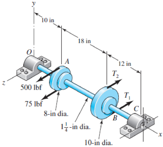
A countershaft carrying two V-belt pulleys is shown in the figure. Pulley A receives power from a motor through a belt with the belt tensions shown. The power is transmitted through the shaft and delivered to the belt on pulley B. Assume the belt tension on the loose side at B is 15 percent of the tension on the tight side.
(a) Determine the tensions in the belt on pulley B, assuming the shaft is running at a constant speed.
(b) Find the magnitudes of the bearing reaction forces, assuming the bearings act as simple supports.
(c) Draw shear-force and bending-moment diagrams for the shaft. If needed, make one set for the horizontal plane and another set for the vertical plane.
(d) At the point of maximum bending moment, determine the bending stress and the torsional shear stress.
(e) At the point of maximum bending moment, determine the principal stresses and the maximum shear stress.
Problem 3–68*
The factor of safety for yielding from maximum-shear-stress theory.
The factor of safety for yielding from distortion-energy theory.
Answer to Problem 39P
The factor of safety for yielding from maximum-shear-stress theory is
The factor of safety for yielding from distortion-energy theory is
Explanation of Solution
The Free body diagram of pulley
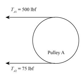
Figure-(1)
The free body diagram of pulley
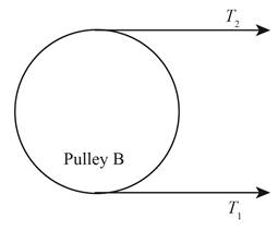
Figure-(2)
The given assumption is that the belt tension on the loose side at
Write the relationship between tension on the loose side with respect to tension on the tight side.
Here, the tension on the loose side is
Write the equation to balance the tension on the counter shaft.
Here, the tension on the tight side of pulley
Substitute
Write the tension on the loose side.
Write the magnitude of bearing reaction force at
Here, the magnitude of the bearing force at
Write the magnitude of bearing reaction force at
Here, the magnitude of bearing reaction force at
Write the shear force at
Here, the shear force at
Write the shear force at
Here, the shear force at
Write the shear force at
Here, the shear force at
Write the shear force at
Here, the shear force at
We know that, the moment at the supports of the simply supported beam is zero.
Write the moment at
Here, the moment at
Write the moment at
Here, the moment at
Write the moment at
Here, the moment at
It is clear from the shear force diagram and bending moment diagram of the shaft that the point of maximum bending moment is at
Write the torque acting at pulley
Here, the torque acting on pulley
Write the bending stress.
Here, the bending stress is
Write the shear stress.
Here, the shear stress is
Write the maximum principal stress.
Here, the maximum principal stress is
Calculate the minimum principal stress.
Here, the minimum principal stress is
Write the maximum shear stress.
Here, maximum shear stress is
Calculate the factor of safety from maximum-shear-stress theory.
Here, the maximum yield stress for
Calculate the factor of safety from distortion-energy theory.
Here, the Von Mises stress is
Write the expression for von Mises stress.
Substitute
Conclusion:
Substitute
Substitute
Substitute
Substitute
Substitute
Substitute
Substitute
Substitute
Substitute
Substitute
The shear force diagram and bending moment diagram for the shaft is as follows.
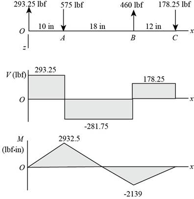
Figure-(3)
Substitute
Substitute
Substitute
Substitute
Substitute
Substitute
Refer to the Table A-20 “Deterministic ASTM Minimum Tensile and Yield Strengths for Some Hot-Rolled (HR) and Cold-Drawn (CD) Steels” to obtain the yield strength of
Substitute
Thus, the factor of safety for yielding from maximum-shear-stress theory is
Substitute
Thus, the factor of safety for yielding from distortion-energy theory is
Want to see more full solutions like this?
Chapter 5 Solutions
Shigley's Mechanical Engineering Design (McGraw-Hill Series in Mechanical Engineering)


- Solve the preceding problem if the thickness of the steel plate is. t = 12 mm. the gage readings are x = 530 × 10-6 (elongation) and y = -210 -× l0-6 (shortening), the modulus is E = 200 GPa, and Poisson’s ratio is v = 0.30.arrow_forwardSolve the preceding problem for the following data:P = 160 kN,JV = 200 tN,L = 2 m,b = 95 mm, h = 300 mm, and d = 200 mmarrow_forwardA polyethylene tube (length L) has a cap that when installed compresses a spring (with under-formed length L1) by an amount ?? = (L1 = L). Ignore deformations of the cap and base. Use the force at the base of the spring as the redundant. Use numerical properties given in the boxes. (a) What is the resulting Force-in the spring, Fk? (b) What is the resulting Force in the tube, Ftl (c) What is the filial length of the tube, Lf? (d) What temperature change ?T inside the tube will result in zero force in the springarrow_forward
- Two sections of steel drill pipe, joined by bolted flange plates at Ä are being tested to assess the adequacy of both the pipes. In the test, the pipe structure is fixed at A, a concentrated torque of 500 kN - m is applied at x = 0.5 m, and uniformly distributed torque intensity t1= 250 kN m/m is applied on pipe BC. Both pipes have the same inner diameter = 200 mm. Pipe AB has thickness tAB=15 mm, while pipe BC has thickness TBC= 12 mm. Find the maximum shear stress and maximum twist of the pipe and their locations along the pipe. Assume G = 75 GPa.arrow_forwardThe strength-to-weight ratio of a structural material is defined as its load-carrying capacity divided by its weight. For materials in tension, use a characteristic tensile stress obtained from a stress-strain curve as a measure of strength. For instance, either the yield stress or the ultimate stress could be used, depending upon the particular application. Thus, the strength-to-weight ratio RS/Wfor a material in tension is defined as Rs/w= in which a is the characteristic stress and 7 is the weight density. Note that the ratio has units of length. Using the ultimate stress Uas the strength parameter, calculate the strength-to-weight ratio (in units of meters) for each of the following materials: aluminum alloy 606I-T6, Douglas fir (in bending}, nylon. structural steel ASTM-A57.2, and a titanium alloy. Obtain the material properties from Tables [-1 and 1-3 of Appendix I. When a range of values is given in a table, use the average value.arrow_forwardA hollow circular tube A fits over the end of a solid circular bar B, as shown in the figure. The far ends of both bars are fixed. Initially, a hole through bar B makes an angle ß with a line through two holes in tube A. Then bar B is twisted until the holes are aligned, and a pin is placed through the holes. When bar B is released and the system returns to equilibrium, what is the total strain energy U of the two bars? (Let lAand lBrepresent the polar moments of inertia of bars A and B, respectively. The length L and shear modulus of elasticity G are the same for both bars.)arrow_forward
- A circular steel tube with an outer diameter of 75 mm and inner diameter of 65 mm is subjected to torques 7"at its ends. Calculate the maximum permissible torque 7jliajl if the allowable normal strain is ea= 5 X 10"4 Assume that G = 15 GPa.arrow_forwardA crank arm consists of a solid segment of length bxand diameter rf, a segment of length bltand a segment of length byas shown in the figure. Two loads P act as shown: one parallel to — vand another parallel to —y. Each load P equals 1.2 kN. The crankshaft dimensions are A] = 75 mm, fr> = 125 mm, and b3= 35 mm. The diameter of the upper shaft isd = 22 mm, (a) Determine the maximum tensile, compressive, and shear stresses at point A, which is located on the surface of the shaft at the z axis. (b) Determine the maximum tensile, compressive, and shear stresses at point B, which is located on the surface of the shaft at the y axisarrow_forwardRequired information This problem illustrates that the factor of safety for a machine element depends on the particular point selected for analysis. Here you are to compute factors of safety, based upon the distortion-energy theory, for stress elements at A and B of the member shown in the figure. This bar is made of AISI 1006 cold-drawn steel and is loaded by the forces F= 0.55 kN, P= 4 kN, and T=25 N-m. Given: Sy= 280 MPa. NOTE: This is a multi-part question. Once an answer is submitted, you will be unable to return to this part. B 15-mm D. -100 mm What is the value of the axial stress at point A? The value of the axial stress at point A is MPa.arrow_forward
- 2. The following handle is loaded at points B and C, as shown below. 0.8 m 40 mm 0.4 m If the force P = 20F, and the material of the handle has Sy = 250 MPa: a. Show the stress state at element A. b. Using the distortion energy theory, find the maximum force F that guarantees a safety factor of 1.4.arrow_forwardThis problem illustrates that the factor of safety for a machine element depends on the particular point selected for analysis. Here you are to compute factors of safety, based upon the distortion-energy theory, for stress elements at A and B of the member shown in the figure. This bar is made of AISI 1006 cold-drawn steel and is loaded by the forces F = 0.55 kN, P = 8.0 kN, and T = 30 N m = 280 MPa 100 mm A B d=20 mmarrow_forwardConsider a machine element as shown in the figure. The stress element at a critical point on this element is shown. Determine the smallest yield stress for a steel that can be selected for the member, based on the maximum-shear-stress theory. What result you expect if maximum distortion energy theory is used. 80ksi 25 ksiarrow_forward
 Mechanics of Materials (MindTap Course List)Mechanical EngineeringISBN:9781337093347Author:Barry J. Goodno, James M. GerePublisher:Cengage Learning