
Concept explainers
Videos
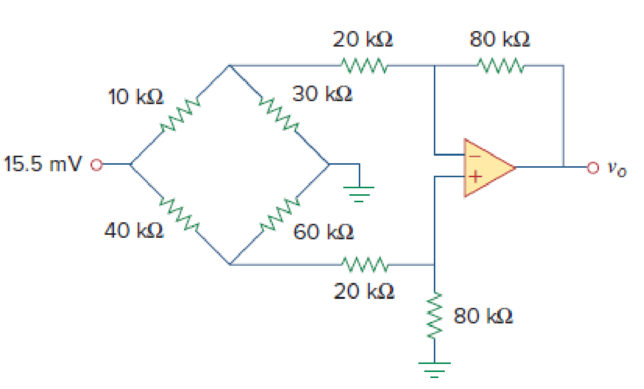
The circuit in Fig. 5.80 is a differential amplifier driven by a bridge. Find vo.
Calculate the output voltage
Answer to Problem 48P
The output voltage
Explanation of Solution
Given data:
Refer Figure 5.80 in the textbook for the differential amplifier that is driven by a bridge circuit.
Calculation:
Consider break this problem up into parts. The 15.5 mV voltage source splits the lower circuit from the upper circuit. In addition, there is no current flowing into the op amp input which means we now have the
Consider the expression for the current flows through the circuit.
Substitute 15.5 mV for
The voltage across the
Substitute
The voltage across the
This voltage is also the voltage at both inputs of the op amp and the voltage between the
Modify Figure 5.80 by indicating the node voltages. The modified figure as shown in Figure 1.
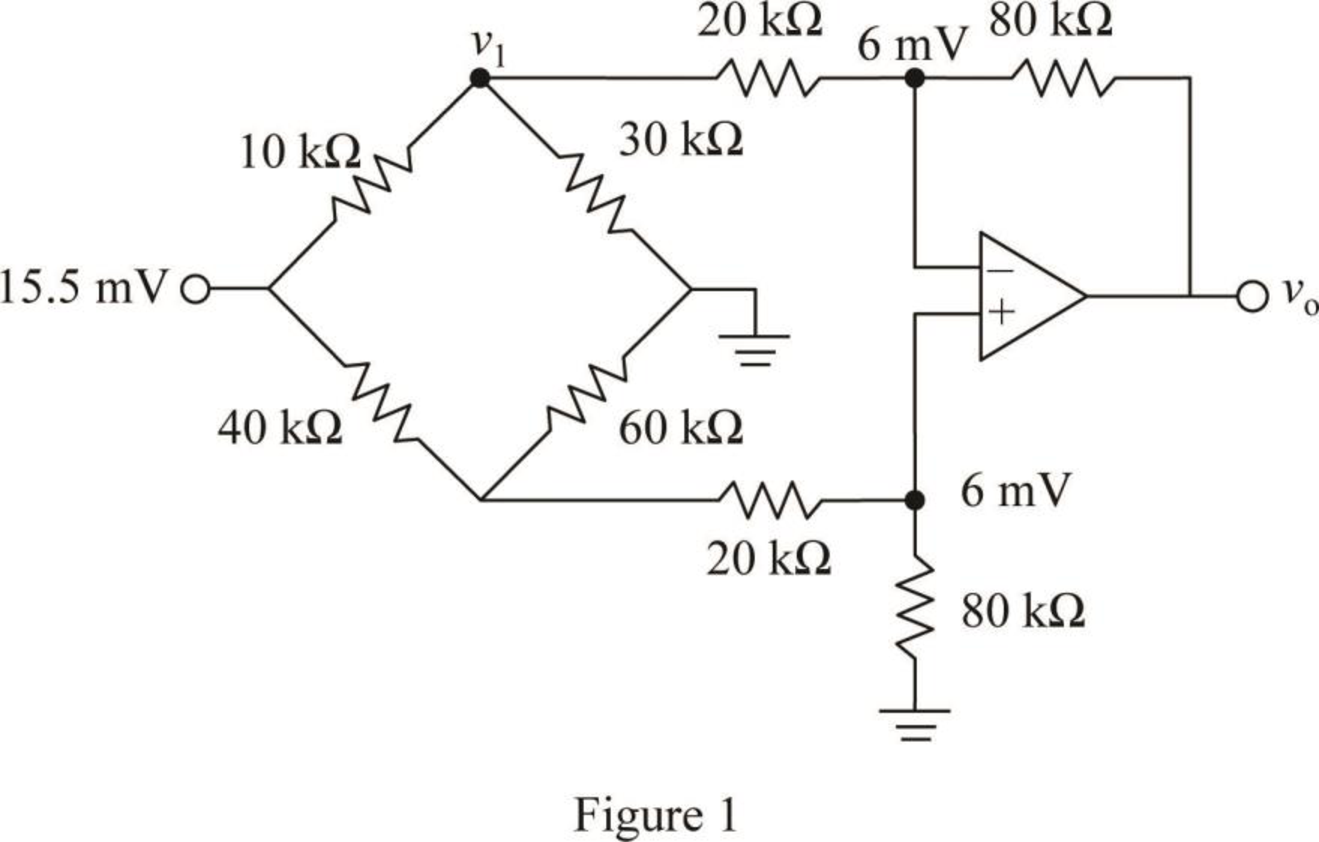
Write a node equation at node
Consider the expression for the current through the
Substitute 10.091 mV for
Write the expression for the output voltage
Substitute
Conclusion:
Thus, the output voltage
Want to see more full solutions like this?
Chapter 5 Solutions
Fundamentals of Electric Circuits


- The Junction Gate Field Effect Transistor is one of the simplest types of fieldeffect transistor. It is a three-terminal semiconductor device .One of its function is, it serve as an amplifier. As an Engineer you are to design a single stage JFET Amplifier. Explain in your own words this circuit operates, identifyingarrow_forwardThe beta of each transistor in the ideal differential amplifier shown in Figure 5-77 (p. 255) is 100. Find (a) the dc output voltages VO1 and VO2.arrow_forwardKindly create a circuit with amplifier with DC power supply and with a gain of 150 with a closed circuit. Kindly provide explanation on how it operates thankyouarrow_forward
- Find v, in the op amp circuit shown in Fig. 5.23. 3R, SR, Ro SR,arrow_forward2K The op amp used in the inverting amplifier circuit is not ideal. In fact, it is an LM741 with the following parameters: v W Rin = 2 MQ, AoL = 200 V/mV, Rout = 200 Q. Determine the gain vo/vi of the op amp circuit. If the gain computed in a is the actual gain, what is the percentage accuracy of the computed gain if the op amp is considered ideal? 4. 1K vo а. b.arrow_forward5.71 Determine v, in the op amp circuit of Fig. 5.97. 20 k2 100 k2 5 k2 ww 40 k2 ww ww 80 k2 2 V 10 kΩ 20 k2 10 k2 ww 3 V 50 k2 30 k2 wwarrow_forward
- The op amp shown is ideal. Find vo if va=1.2 V, vb=-1.5 V, and vc=4 V.arrow_forwarda common-collector (CC) amplifier has an input resistance of 5K ohms and a load resistance of 100 ohms . the power gain is 50 Select one: True Falsearrow_forwardb. Your high-fidelity amplifier has one output for a speaker whose resistance is 8 0. How can you arrange two 8-Q speakers, one 4-0 speaker, and one 12-0 speaker so that all are powered by the amplifier and their equivalent resistance when connected together in this way is exactly 8 Q. Draw the circuit diagram and support it with computation.arrow_forward
 Delmar's Standard Textbook Of ElectricityElectrical EngineeringISBN:9781337900348Author:Stephen L. HermanPublisher:Cengage Learning