
Concept explainers
Videos
Given the op amp circuit shown in Fig. 5.72, express vo in terms of v1 and v2.
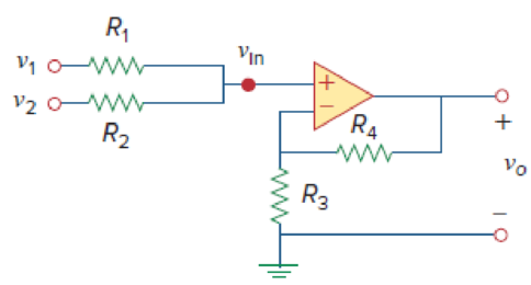
Figure 5.72
For Prob. 5.34.
State the expression for the voltage
Answer to Problem 34P
The expression for the voltage
Explanation of Solution
Given data:
Refer Figure 5.72 in the textbook for the op amp circuit.
Calculation:
Consider that the given circuit is a non-inverting amplifier.
Modify to the Figure 5.72 by indicating the node voltage
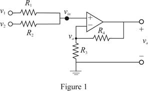
In Figure 1, write the expression by the use of Kirchhoff's current law.
Re-arrange the equation.
Consider the expression for the voltage
Substitute
Consider the expression for voltage
Re-arrange equation (2).
Multiply
Substitute equation (3) in (4).
Conclusion:
Thus, the expression for the voltage
Want to see more full solutions like this?
Chapter 5 Solutions
Fundamentals of Electric Circuits


- 5.2. Determine V out as a function of I (provided by a current source) and the resistor values for each of the op amp circuits that follows. Assume ideal op amp behavior. Vout R1 (a) I R2 R3 R4 R3 R1 (b) I V. out R2arrow_forward5.39 For the op amp circuit in Fig. 5.76, determine the value of v2 in order to make v, = -16.5 V. 10 k2 50 k2 -3 V O 20 k2 V2 O + 50 k2 5 V oarrow_forwardGiven the circuit (inverted op amp) how do I find my input voltage?arrow_forward
- 5.17 Investigate the effect of using an op amp with CMRRdB = 100 dB on the output resis- tance of a Howland current pump made up of four perfectly matched 10-k2 resistances. Except for CMRR. the op amp is ideal. R W IND IP 4 W (a) FIGURE 5.7 R R₂ O vo 7arrow_forward5.59 In the op amp circuit of Fig. 5.86, determine the voltage gain v,/vg. Take R = 10 k2. 2R 4R R R Vsarrow_forwardProblem (1): Section 5.3 Ideal Op Amp 5.8 Obtain v, for each of the op amp circuits in Fig. 5.47. 1 mA Figure 5.47 ForProb. 5.8. (a) 2 ΚΩ wwww +1. 9+19 2 V 1 V 10 ΚΩ www 2 ΚΩ Voarrow_forward
- Practice (4.2): Repeat Example 5.1 using the ideal op amp model. Ans: -2, 200 uA. 20 k2 10 k2 1 741 Vs Fig. (4.6) ahme91.d |Earrow_forwardFor the op amp circuit, find the voltage gain vo/vs. assume R1= 100 ohms, R2= 150 ohms, Rf= 500 ohmsarrow_forwardFigure 5.52 For Prob. 5.13. 5.14 Determine the output voltage v, in the circuit of Fig. 5.53. 10 k2 10 kQ 20 kQ 5 mA 5 k2 Figure 5.53 For Prob. 5.14. er work. Section 5.4 Inverting Amplifierarrow_forward
- An op-amp is connected to power supplies so that its Vcc value is 15V. It has an open-loop gain of 8 x 10⁶ V/V, and the non-inverting input is 1 µV. If the output voltage is equal to 2V, what is the magnitude of the voltage connected to the inverting terminal?arrow_forwardR4 As R3 R Figure 5.26 Instrumentation amplifier; for Example 5.8. Since the op amps Aj and A2 draw no current, current i flows through the three resistors as though they were in series. Hence, Vol - vo2 = i (R3 + R4 + R3) =i (2R3 + R4) (5.8.2) But Va - U i = RA and v, = v1, vh = v2. Therefore, vi - v2 i = R4 (5.8.3) Inserting Eqs. (5.8.2) and (5.8.3) into Eq. (5.8.1) gives R2 Vo = 2R3 + (v2 – v1) R4 as required. We will discuss the instrumentation amplifier in detail in Section 5.10. ROBLEM 5.8 Obtain i, in the instrumentation amplifier circuit of Fig. 5.27. 8.00 V o 40 ka ww- 20 k2 ww- -ww 20 k2 8.01 V o 40 k2 10 kn Figure 5.27 Instrumentation amplifier; for Practice Prob. 5.8. Answer: 2 µA. CНАРТER 5 Operational Amplifiers 181 DED OP AMP CIRCUITS amp circuits are modules or building blocks for designing s. It is often necessary in practical applications to connect in cascade (i.e., head to tail) to achieve a large overall 1, two circuits are cascaded when they are connected in ind…arrow_forwardAssuming an ideal op amp, design and draw the circuits for the following. Your resistor values must be between 1k and 100k, inclusive. (a) An op amp circuit with a gain of -5 V/V (b) An op amp circuit with a gain of 3 V/Varrow_forward
 Introductory Circuit Analysis (13th Edition)Electrical EngineeringISBN:9780133923605Author:Robert L. BoylestadPublisher:PEARSON
 Delmar's Standard Textbook Of ElectricityElectrical EngineeringISBN:9781337900348Author:Stephen L. HermanPublisher:Cengage Learning
 Programmable Logic ControllersElectrical EngineeringISBN:9780073373843Author:Frank D. PetruzellaPublisher:McGraw-Hill Education
 Fundamentals of Electric CircuitsElectrical EngineeringISBN:9780078028229Author:Charles K Alexander, Matthew SadikuPublisher:McGraw-Hill Education
 Electric Circuits. (11th Edition)Electrical EngineeringISBN:9780134746968Author:James W. Nilsson, Susan RiedelPublisher:PEARSON
 Engineering ElectromagneticsElectrical EngineeringISBN:9780078028151Author:Hayt, William H. (william Hart), Jr, BUCK, John A.Publisher:Mcgraw-hill Education,