
Concept explainers
Videos
The two input terminals of an op amp are labeled as:
- (a) high and low.
- (b) positive and negative.
- (c) inverting and noninverting.
- (d) differential and nondifferential.
Find the correct option, which provides the two terminals of an op amp.
Answer to Problem 1RQ
The option is (c) inverting and noninverting.
Explanation of Solution
Calculation:
Operational amplifier (Op amp):
An active circuit element, which consists of complex arrangement of transistors, resistors, capacitors and diodes to perform various operations, is known as operational amplifier.
The general electronic symbol of op amp is shown in Figure 1.
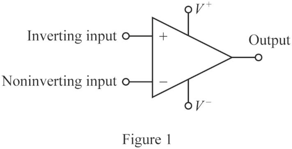
In Figure 1, the op amp has two inputs and one output. Two input terminals are named as inverting input and noninverting input terminals.
The inputs marked with the notations
Therefore, the option (c) is correct and the options (a), (b), (d) are incorrect.
Conclusion:
Thus, the correct option is (c) inverting and noninverting.
Want to see more full solutions like this?
Chapter 5 Solutions
Fundamentals of Electric Circuits
Additional Engineering Textbook Solutions
Introductory Circuit Analysis (13th Edition)
Electric Circuits (10th Edition)
Basic Engineering Circuit Analysis
Electric Circuits. (11th Edition)
ANALYSIS+DESIGN OF LINEAR CIRCUITS(LL)
Fundamentals of Applied Electromagnetics (7th Edition)


- The two input terminals of an op-amp are connected to voltage signals of strength 745µV and 740µV repectively. The gain of the op-amp in common mode is 50 and CMMR is 8&IB. Calculate the output voltage and % of error due to common mode.arrow_forwarddraw the block diagram of op-Amparrow_forwardDraw two op-amp circuits: 1. An input voltage is applied to the non-inverting terminal. The inverting terminal is shorted to the output. 2. An input voltage is applied to the inverting terminal. The non-inverting terminal is shorted to the output. Derive the I/O relationship of both of these circuits assuming the op-amps act ideally. Comment on differences/similarities.arrow_forward
- . For the combinational op-amp circuit A. Identify the connection/application of each op-amp: A1, A2, A3 and A4. B. Find V01, V02, V03, and V0.arrow_forwardIf the output polarity is same as that of input polarity but with amplification, then it should be a type of op amp circuit Select one: a. Voltage Follower b. Inverting Amplifier c. Summer Amplifier d. Non-inverting amplifierarrow_forward1- Mention any two non linear applications of op- amp. 2- For the circuit given below : Vin is a sine wave Vinpp=9 V and Vref=2.4 V , Assume Vsat=±12V Name the circuit and draw the input and output waveforms . Vo Vin Vref 3- Explain why open-loop op-amp configurations are not used in linear applications? Draw the block diagram of opamp and define the function of each blockarrow_forward
- the output of an op amp is affected by the input offset voltage,input offset current, input biassing current , the power supply,input frequency?? ( true or false) and why ?arrow_forwardThe output of an op-amp comparator will change of state when the input voltage exceeds the reference voltage. Select one: True Falsearrow_forward1) Op-amp limiting factors - Current Saturation U2 Vin R1 OUT OPAMP R2 RLoad The saturation output current for the above op-amp is +/- 15mA. For the following input signals, determine if the output appears as would be expected in an ideal circuit. Include sketches of the output voltage. a) R1 = 100, R2 = 900, an open circuit load, and Vin is 2Vpp triangle wave with zero offset voltage (Vmax 1V, Vmin = -1V) and a period of 2ms. b) R1 = 100, R2 = 900, a 1k load, and Vin is 2Vpp triangle wave with a 1V offset voltage (Vmax=2V, Vmin = 0V) and a period of 2ms. c) R1 = 100, R2 = 900, an open circuit load, and Vin is 4Vpp triangle wave with zero offset voltage (Vmax=2V, Vmin = -2V) and a period of 2ms.arrow_forward
- In practical sense, explain why an op-amp will have an output voltage even if its input voltage is zero.arrow_forwardI am unsure of how to find the equivalent resistance I suspect that I have to transform this into a "realistic/non-ideal" op-amp but I don't know.arrow_forwardProblem C It is desired to have a gain of 20 for frequencies up to 180 kHz. Determine the minimum unity gain frequency specification for the op amp. The gain should be within at least 98% Vsig Rin + Rf Vcc/-Vcc +12v/ -12V Voutarrow_forward
 Introductory Circuit Analysis (13th Edition)Electrical EngineeringISBN:9780133923605Author:Robert L. BoylestadPublisher:PEARSON
 Delmar's Standard Textbook Of ElectricityElectrical EngineeringISBN:9781337900348Author:Stephen L. HermanPublisher:Cengage Learning
 Programmable Logic ControllersElectrical EngineeringISBN:9780073373843Author:Frank D. PetruzellaPublisher:McGraw-Hill Education
 Fundamentals of Electric CircuitsElectrical EngineeringISBN:9780078028229Author:Charles K Alexander, Matthew SadikuPublisher:McGraw-Hill Education
 Electric Circuits. (11th Edition)Electrical EngineeringISBN:9780134746968Author:James W. Nilsson, Susan RiedelPublisher:PEARSON
 Engineering ElectromagneticsElectrical EngineeringISBN:9780078028151Author:Hayt, William H. (william Hart), Jr, BUCK, John A.Publisher:Mcgraw-hill Education,