
Concept explainers
Videos
(a) Determine the ratio vo/is in the op amp circuit of Fig. 5.54.
(b) Evaluate the ratio for R1 = 20 kΩ, R2 = 25 kΩ, R3 = 40 kΩ.
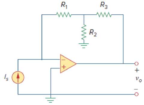
Figure 5.54
For Prob. 5.15.
(a)
Calculate the ratio
Answer to Problem 15P
The ratio
Explanation of Solution
Given data:
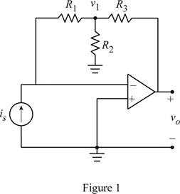
Refer Figure 5.54 in the textbook for the op amp circuit.
Calculation:
Modify the Figure 5.54 by indicating the node voltage
Apply Kirchhoff's current law to the node
Consider the expression for the current
Substitute equation (2) in (1).
Simplify the equation as follows.
Conclusion:
Thus, the ratio
(b)
Find the value for the ratio
Answer to Problem 15P
The value for
Explanation of Solution
Given data:
Consider that the resistors
Calculation:
Substitute
Conclusion:
Thus, the value for
Want to see more full solutions like this?
Chapter 5 Solutions
Fundamentals of Electric Circuits


- 3. Problem 5.29: Determine the voltage gain vo/vi of the following OP Amp circuit R1 R2 R2 R1arrow_forward5.39 For the op amp circuit in Fig. 5.76, determine the value of v2 in order to make v, = -16.5 V. 10 k2 50 k2 -3 V O 20 k2 V2 O + 50 k2 5 V oarrow_forward5.2. Determine V out as a function of I (provided by a current source) and the resistor values for each of the op amp circuits that follows. Assume ideal op amp behavior. Vout R1 (a) I R2 R3 R4 R3 R1 (b) I V. out R2arrow_forward
- R1 = 6 k2 and R2 = 13 k2, determine the output voltage vo. Please pay attention: the 5.21 For the circuit involving an ideal op amp shown in the image below, numbers may change since they are randomized. Your answer must include 2 places after the decimal point, and the proper SI unit. R2 R1 6 V (+ 4 V Vo Your Answer: Answer units 19arrow_forward5.59 In the op amp circuit of Fig. 5.86, determine the voltage gain v,/vg. Take R = 10 k2. 2R 4R R R Vsarrow_forwardHW26 5.70 Determine v, in the op amp circuit of Fig. 5.96. 30 ΚΩ 40 kQ ww ww 10 ΚΩ A 20 k2 ww- 1V 60 kQ 10 k2 ww 10 k2 2 V 20 Ω w 10 k2 ww В 3V 10 k2 4V 14 wwHarrow_forward
- 5.39 For the op amp circuit in Fig. 5.74, determine the value of v2 in order to make vo = -16.5 V. 10 ΚΩ +2VO www 20 ΚΩ 22 OM 50 ΚΩ -1 V O www Ans: V2 = 3 volts 50 ΚΩ www Voarrow_forwardDetermine Vo and io in the Op-Amp circuit shown in the figure below. www www 62 6k2 6k2 대회 12V 6k2 6k2.arrow_forward5.67 Obtain the output v, in the circuit of Fig. 5.94. 80 k2 80 k2 20 k2 40 k2 ww- 0.4 V 20 k2 0.2 V Figure 5.94 For Prob. 5.67.arrow_forward
- + des y S, ng lues of Section 5.7 Difference Amplifier 5.47 The circuit in Fig. 5.79 is for a difference amplifier. Find v, vo given that v₁ = 1 V and v₂ = 2 V. V₁ + V2 PR 2 ΚΩ ww +1 Figure 5.79 For Prob. 5.47. 2 ΚΩ ww S www C 20 ΚΩ 30 ΚΩ ww 5.48 The circuit in Fig. 5.80 is a differential amplifier driven by a bridge. Find vo. + I + o Vo 10arrow_forward5.74 Find i, in the op amp circuit of Fig. 5.100. 0.9 V 10 ΚΩ Μ 100 ΚΩ Μ 20 ΚΩ 32 ΚΩ 1.6 ΚΩ 0.6 Varrow_forwardQ-5. Assuming ideal op amps, find the voltage gain of each of the circuits. 100 k2 100 kN 100 kN 100 k2 10 kN 10 k2 10 kN 10 kN O vo 10 kN = 10 kN 10 kNarrow_forward
 Introductory Circuit Analysis (13th Edition)Electrical EngineeringISBN:9780133923605Author:Robert L. BoylestadPublisher:PEARSON
 Delmar's Standard Textbook Of ElectricityElectrical EngineeringISBN:9781337900348Author:Stephen L. HermanPublisher:Cengage Learning
 Programmable Logic ControllersElectrical EngineeringISBN:9780073373843Author:Frank D. PetruzellaPublisher:McGraw-Hill Education
 Fundamentals of Electric CircuitsElectrical EngineeringISBN:9780078028229Author:Charles K Alexander, Matthew SadikuPublisher:McGraw-Hill Education
 Electric Circuits. (11th Edition)Electrical EngineeringISBN:9780134746968Author:James W. Nilsson, Susan RiedelPublisher:PEARSON
 Engineering ElectromagneticsElectrical EngineeringISBN:9780078028151Author:Hayt, William H. (william Hart), Jr, BUCK, John A.Publisher:Mcgraw-hill Education,