
Concept explainers
(a)
The force
(a)
Answer to Problem 73P
The force
Explanation of Solution
The figure below shows the free body diagram of pulley A.
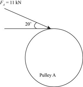
Figure-(1)
The figure below shows the free body diagram of pulley B.
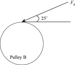
Figure-(2)
Convert the forces from
Calculate the force
Here, the force acting on pulley
Conclusion:
Substitute
Thus, the force
(b)
The bearing reaction forces, assuming the bearing act as simple supports.
(b)
Answer to Problem 73P
The bearing reaction forces, assuming the bearing act as simple supports at
Explanation of Solution
Write the expression for moment about bearing
Here, the reaction force at bearing
Write expression for the equation to balance the forces in
Here, the reaction force at bearing
Write expression for the moment about bearing
Here, the reaction force at bearing
Write expression for the equation to balance the forces in
Here, the reaction force at bearing
Calculate the reaction forces at bearing
Here, the reaction force at bearing
Calculate the reaction forces at bearing
Here, the reaction force at bearing
Conclusion:
Substitute
Convert
Substitute
Substitute
Substitute
Substitute
Substitute
Thus, the bearing reaction forces, assuming the bearing act as simple supports at
(c)
The shear force and bending moment diagram for the shaft.
(c)
Answer to Problem 73P
The shear force and bending moment diagram for the shaft in
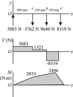
Figure-(2)
The shear force and bending moment diagram for the shaft in
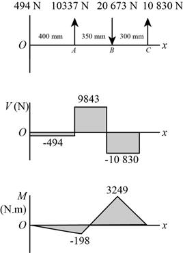
Figure-(3)
Explanation of Solution
The calculations for shear force and bending moment diagram in
Calculate the shear force at
Here, the shear force at
Calculate the shear force at
Here, the shear force at
Calculate the shear force at
Here, the shear force at
Calculate the shear force at
Here, the shear force at
Calculate the moment at
Here, the moment at
Calculate the moment at
Here, the moment at
Calculate the moment at
Here, the moment at
Conclusion:
Substitute
Substitute
Substitute
Substitute
Substitute
Substitute
Thus, the shear force and bending moment diagram in

Figure-(4)
Substitute
Substitute
Substitute
Substitute
Substitute
Substitute
Thus, the shear force and bending moment diagram in

Figure-(5)
(d)
The bending stress at point of maximum bending moment.
The shear stress at point of maximum bending moment.
(d)
Answer to Problem 73P
The bending stress at point of maximum bending moment is
The shear stress at point of maximum bending moment is
Explanation of Solution
Write the net moment at
Here, the net moment at
Write the net moment at
Here, the net moment at
Write the torque transmitted by shaft from
Here, the torque transmitted by shaft from
Calculate the bending stress.
Here, the bending stress is
Calculate the shear stress.
Here, the shear stress is
Conclusion:
Substitute
Substitute
Since,
Substitute
Substitute
Thus, the bending stress at point of maximum bending moment is
Substitute
Thus, the shear stress at point of maximum bending moment is
(e)
The principal stresses at point of maximum bending moment.
The maximum shear stress at point of maximum bending moment.
(e)
Answer to Problem 73P
The principal stresses at point of maximum bending moment are
The maximum shear stress at point of maximum bending moment is
Explanation of Solution
Calculate the maximum principal stress.
Here, the maximum principal stress is
Calculate the minimum principal stress.
Here, the minimum principal stress is
Calculate the maximum shear stress.
Here, maximum shear stress is
Conclusion:
Substitute
Substitute
Thus, the principal stresses at point of maximum bending moment are
Substitute
Thus, the maximum shear stress at point of maximum bending moment is
Want to see more full solutions like this?
Chapter 3 Solutions
Shigley's Mechanical Engineering Design (McGraw-Hill Series in Mechanical Engineering)


- A motor driving a solid circular steel shaft with diameter d = 1.5 in, transmits 50 hp to a gear at B, The allowable shear stress in the steel is 6000 psi. Calculate the required speed of rotation (number of revolutions per minute) so that the shear stress in the shaft does not exceed the allowable limit.arrow_forwardIn the fabric dye-printing system given in the figure, the motion is transmitted from the electric motor to the drum of the machine. There is a two-stage reducer in between. Number of teeth of gears z1=17; z2=85; z3=18; z4=72; The efficiency of a pair of gears is given as na=0.97 and the efficiency of each of the gearbox shafts and lower bearing pairs to the drum bearing is given as n=0.97. The diameter of the drum will be D=200 mm, the fabric speed will be v=1 m/s and the pulling force required to activate the band will be taken as F-2000 N. a) Find the number of revolutions of the engine. b) Find the required engine power.arrow_forwardIn the gear system shown in the figure, the motor applies a torque of 231 N-m to the gear at A. A torque of TC = 440 N-m is removed from the shaft at gear C, and the remaining torque is removed at gear D. Segments (1) and (2) are solid 38-mm-diameter steel (G = 80 GPa) shafts, and the bearings shown allow free rotation of the shaft. Assume DA = 110 mm, DB = 370 mm, L1 = 1.7 m, and L2 = 1.1 m. Calculate the rotation angle of gear D relative to gear B. Express your answer in radian rounded to the nearest thousandths.arrow_forward
- Shaft a in the figure has a power input of 75 kW at a speed of 1000 rev/min in the counterclock-wise direction. The gears have a module of 5 mm and a 20° pressure angle. Gear 3 is an idler.(a) Find the force F3b that gear 3 exerts against shaft b.(b) Find the torque T4c that gear 4 exerts on shaft c.arrow_forwardFor the gear mechanism in the figure: P1 = 4 kW, η1 = 1000 rpm, z1 = 18, z2 = 36, z3 = 54, z4 = 108, z1 is the driving gear. Total efficiency values for each stage; Since η12 = η34 = 0.96; Find the output torque and speed of gear z4.arrow_forwardA gear train is composed of four helical gears with the three shaft axes in a single plane, as shown in the figure. The gears have a normal pressure angle of 20 and a 30 helix angle. Gear is the driver, and is rotating counterclockwise as viewed from the top. Shaft b is an idler and the transmitted load from gear 2 to gear 3 is 500 Ibf. The gears on shaft b both have a normal diametral pitch of 7 teeth/in and have 54 and 14 teeth, respectively. Find the forces exerted by gears 3 and 4 on shaft barrow_forward
- In the figure below, a motor with power 150kw and speed of 2500 rpm is connected to shaft 1(by coupling) in a clockwise direction. Shaft 2 is connected to shaft 1 by gears 1 and 2. If 30% of the power is consumed by the gear3 and 9% by the pulley and 61% by the sprocket, draw torque diagrams for both shafts. If the pressure angle of the gears is 20 degrees to the x-axis, Calculate the reaction forces of the bearings and draw the bending moment diagrams for both shafts according to the information below: Lengths: AB=90mm/BC=DGH=50mm/CD=HI=60mm/DE=IJ=80mm Diameters: dG1=dG2=47mm/ dG3=20mm/ d(pulley)=35mm/d(sprocket)=40mm Gears Gear2 Tew) shaftz Bearing Shaft Gear1 SProcketarrow_forwardA gear train is composed of four helical gears with the tree shaft axes in a single plane, as shown in the figure. The gears have a normal pressure angle of 20° and a 30°helix angle. Gear 2 is the driver, and is rotating counterclockwise as viewed from the top. Shaft b is and idler and the transmitted load from gear 2 to gear 3 is 500 lbf. The gears on shaft b both have a normal diametral pitch of 7 teeth/in and have 54 and 14 teeth, respectively. Find the forces exerted by gears 3 and 4 on shaft b.arrow_forwardShaft a in the figure has a power input of 75 kW at a speed of 1000 rev/min in the counterclockwise direction. The gears have a module of 5 mm and a 20° pressure angle. Gear 3 is an idler (b) Find the torque T4c that gear 4 exerts on shaft c.arrow_forward
- The intermediate shaft of a two-stage gearbox is given in the figure. P = 4 kW power is transmitted at n = 150 rpm with the help of two helical gears on the shaft.The forces acting on the gears are given as Ft1 = 5092 N, Fr1 = 1972 N, Fa1 = 1853 N, Ft2 = 2546 N, Fr2 = 986 N, Fa2 = 926 N. Diameter of small helical gear d1 = 100 mm, largethe diameter of the gear is d2 = 200 mm. Shaft material yield strength 335 MPa, tensile strength 600 MPa, Kç = 1.95, ka = 0.895, kb = 0.90 and safety coefficient = 1.4now thatarrow_forward3. An 8-m steel shaft rotating at 180 rpm has 70kW applied at a gear that is 3.0m from the left end where another 60kW are applied. The shaft in between the two gears is solid with diameter=40mm. At the right end, 80kW are removed and another 50kW leaves the shaft at 3.60m from the right end. The shaft is hollow between these gears with outside diameter=80mm and inside diameter=70mm. The shaft between the 7OKW and 50kW is hollow with outside diameter=60mm and inside diameter=50mm (a) Find the stresses in each shaft. (b) Determine the angle (in radians) by which one end of the shaft lags behind the other end. Use G=83GPa. 4. Draw the shear and moment diagram and determine the maximum shear and the maximum moment and their location. 5 kN/m A 4.0 m 6.0 m 2.0 m 3/4 0..arrow_forward2- The motor in the figure applies 50 Nm torsion (torque) to the AB shaft. This torque is transferred to the CD shaft with the help of gears at points E and F. Bearings at B, C and D points provide free rotation to the shafts. Calculate the torque T' on the CD Shaft?arrow_forward
 Mechanics of Materials (MindTap Course List)Mechanical EngineeringISBN:9781337093347Author:Barry J. Goodno, James M. GerePublisher:Cengage Learning