
Concept explainers
Videos
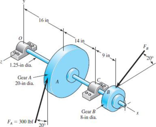
A gear reduction unit uses the countershaft shown in the figure. Gear A receives power from another gear with the transmitted force FA applied at the 20° pressure angle as shown. The power is transmitted through the shaft and delivered through gear B through a transmitted force FB at the pressure angle shown.
(a) Determine the force FB, assuming the shaft is running at a constant speed.
(b) Find the bearing reaction forces, assuming the bearings act as simple supports.
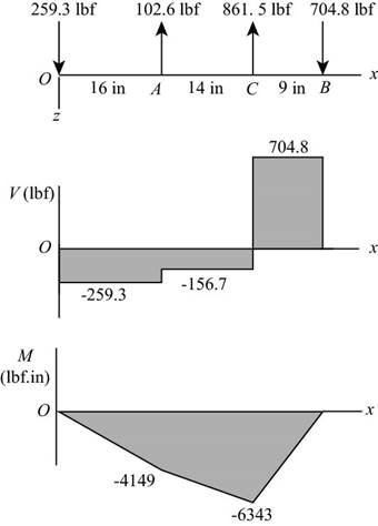
(c) Draw shear-force and bending-moment diagrams for the shaft. If needed, make one set for the horizontal plane and another set for the vertical plane.
(d) At the point of maximum bending moment, determine the bending stress and the torsional shear stress.
(e) At the point of maximum bending moment, determine the principal stresses and the maximum shear stress.
Problem 3–72*
(a)
The magnitude of the force acting on the wheel B.
Answer to Problem 72P
The magnitude of the force acting on the wheel B is
Explanation of Solution
The figure below shows the free body diagram of pulley A.
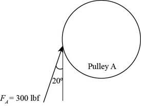
Figure-(1)
The figure below shows the free body diagram of pulley B.
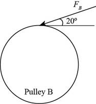
Figure-(2)
Calculate the force
Here, the force acting on pulley
Conclusion:
Substitute
Thus, the force
(b)
The bearing reaction forces at the supports.
Answer to Problem 72P
The bearing reaction at
Explanation of Solution
Write the expression for moment about bearing
Here, the reaction force at bearing
Write the equation to balance the forces in
Here, the reaction force at bearing
Write the expression for moment about bearing
Here, the reaction force at bearing
Write the equation to balance the forces in
Here, the reaction force at bearing
Calculate the reaction forces at bearing
Here, the reaction force at bearing
Calculate the reaction forces at bearing
Here, the reaction force at bearing
Conclusion:
Substitute
Substitute
Substitute
Substitute
Substitute
Thus, the bearing reaction at
Substitute
Thus, the bearing reaction force at
(c)
The shear force and bending moment diagram for the shaft.
Answer to Problem 72P
The shear force and bending moment diagram for the shaft in
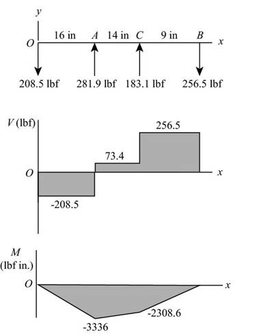
The shear force and bending moment diagram for the shaft in
Explanation of Solution
The calculations for shear force and bending moment diagram in
Calculate the shear force at
Here, the shear force at
Calculate the shear force at
Here, the shear force at
Calculate the shear force at
Here, the shear force at
Calculate the shear force at
Here, the shear force at
Calculate the moment at
Here, the moment at
Calculate the moment at
Here, the moment at
Calculate the moment at
Here, the moment at
Conclusion:
Substitute
Substitute
Substitute
Substitute
Substitute
Substitute
Thus, the shear force and bending moment diagram in
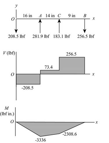
Figure-(3)
Substitute
Substitute
Substitute
Substitute
Substitute
Substitute
Thus, the shear force and bending moment diagram in
Figure-(4)
(d)
The bending stress at point of maximum bending moment.
The shear stress at point of maximum bending moment.
Answer to Problem 72P
The bending stress at point of maximum bending moment is
The shear stress at point of maximum bending moment is
Explanation of Solution
Write the net moment at
Here, the net moment at
Write the net moment at
Here, the net moment at
Write the torque transmitted by shaft from
Here, the torque transmitted by shaft from
Calculate the bending stress.
Here, the bending stress is
Calculate the shear stress.
Here, the shear stress is
Conclusion:
Substitute
Substitute
Since
Substitute
Substitute
Thus, the bending stress at point of maximum bending moment is
Substitute
Thus, the shear stress at point of maximum bending moment is
(e)
The principal stresses at point of maximum bending moment.
The maximum shear stress at point of maximum bending moment.
Answer to Problem 72P
The principal stresses at point of maximum bending moment are
The maximum shear stress at point of maximum bending moment is
Explanation of Solution
Calculate the maximum principal stress.
Here, the maximum principal stress is
Calculate the minimum principal stress.
Here, the minimum principal stress is
Calculate the maximum shear stress.
Here, maximum shear stress is
Conclusion:
Substitute
Substitute
Thus, the principal stresses at the point of maximum bending moment are
Substitute
Thus, the maximum shear stress at point of maximum bending moment is
Want to see more full solutions like this?
Chapter 3 Solutions
Shigley's Mechanical Engineering Design (McGraw-Hill Series in Mechanical Engineering)


- A motor driving a solid circular steel shaft with diameter d = 1.5 in, transmits 50 hp to a gear at B, The allowable shear stress in the steel is 6000 psi. Calculate the required speed of rotation (number of revolutions per minute) so that the shear stress in the shaft does not exceed the allowable limit.arrow_forwardIn the figure below, a motor with power 150kw and speed of 2500 rpm is connected to shaft 1(by coupling) in a clockwise direction. Shaft 2 is connected to shaft 1 by gears 1 and 2. If 30% of the power is consumed by the gear3 and 9% by the pulley and 61% by the sprocket, draw torque diagrams for both shafts. • Lengths: AB=90mm/BC=GH=50mm/CD3HI=60mm/DE=IJ=80mm 13 Gear3 E Gear2 14 15 16 Motor shafth 2. 17 Bearing Shaft1 Gear1 sprocketarrow_forwardA transmission shaft supporting a helical gear B and an overhung bevel gear D is shown in Figure. The shaft is mounted on two bearings, A and C. The pitch circle diameter of the helical gear is 450 mm and the diameter of the bevel gear at the forces is 450 mm. Power is transmitted from the helical gear to the bevel gear. The gears are keyed to the shaft. The material of the shaft is steel 45C8 (ou = 750 N/mm?). The factors kp and k; of ASME code are 2.0 and 1.5 respectively. Determine the shaft diameter using the ASME code. 400 400 400 270 250, 640 210 640 100arrow_forward
- Gear shaft ABCDE is subjected to the torques shown in the figure. Find the internal torque in each seg- ment, and then plot the torsional moment diagram. Assume that the spacing between gears is constant, i.e., 10 in. T1 = T2 = 1000 lb-in. 500 lb-in. A B T3 = 800 Ib-in. C Ta = 500 lb-in. d = 1.0 in. D T; = 800 lb-in. Earrow_forward4. A machine shaft turning at 600 rpm is supported on bearings 30" apart. Twenty HP is supplied to the shaft through an 18" pulley located 10" to the right of the right bearing. The power is transmitted from the shaft through an 8" spur gear located 10" to the right of the left bearing. The pulley weighs 200 lb to provide some flywheel effect. The forces acting on the pulley and the gear are given in the diagram. The shaft material selected has an ultimate strength of 70,000 psi and a yield stress of 46,000 psi, determine: Reactions at the bearings b. Bending moment diagrams in the horizontal and vertical directions a. The necessary diameter in accordance with the ASME Code using Kh=1.5 and Kt = 1.0. points) с. Pulley Mt 525 lb Gear 191 lb Mt Forces on Gear 10" 20" 10" 348 lb W-200 lb 116 lbarrow_forwardDetermine the resisting torque at support A and B , of the shaft shown in the figure.arrow_forward
- A gear reduction unit uses the countershaft shown in the figure. Gear A receives power from another gear with the transmitted force FA applied at the 20 pressure angle as shown. The power is transmitted through the shaft and delivered through gear B through a transmitted force Fg at the pressure angle shown. For the steel countershaft shown below, assume the bearings have a maximum slope specification of 0.064" for good bearing life. Does the dia shown below meet the requirement? if not determine a suitable shaft diameter. 1.25-in da Gear A F₁-300- Gear B Sindia The minimum shaft diameter is in.arrow_forwardShaft a in the figure has a power input of 75 kW at a speed of 1000 rev/min in the counterclock-wise direction. The gears have a module of 5 mm and a 20° pressure angle. Gear 3 is an idler.(a) Find the force F3b that gear 3 exerts against shaft b.(b) Find the torque T4c that gear 4 exerts on shaft c.arrow_forwardRequired information A gear reduction unit uses the countershaft shown in the figure. Gear A receives power from another gear with the transmitted force FA applied at the 20° pressure angle as shown. The power is transmitted through the shaft and delivered through gear B through a transmitted force FB at the pressure angle shown. Given: FA = 450 lbf, diameter of gear A = 19 in, and diameter of gear B=7.6 in. NOTE: This is a multi-part question. Once an answer is submitted, you will be unable to return to this part. 1.25-in dia. FA Gear A 16 in 20⁰° 14 in Gear B 9 in FB 20⁰ Find the bearing reaction forces, assuming the bearings act as simple supports. The magnitude of the bearing reaction force Rcy is The magnitude of the bearing reaction force Roy is The magnitude of the bearing reaction force Rcz is Ibf. lbf. Ibf.arrow_forward
- a) A line shaft as shown in Figure Q is driven using a motor placed vertically below it. The pulley on the line shaft is 1.6 m in diameter and has belt tensions 7.5 kN and 2.4 kN on the tight side and slack side of the belt respectively. Both tensions may be assumed to be vertical and the weight of the pulley is negligible. If the pulley is overhang from the shaft, the distance of the centre line of the pulley from the centre line of the bearing being 500 mm.6.Figure Q(i) Predict using distortion energy theory, the appropriate diameter of the shaft that failure will not occur if the yield strength, Sy = 370 Mpa and factor of safety is 2.5. (ii) Assuming the maximum allowable shear stress of 42 MPa, find its diameter using maximum shear stress theory. (iii) Comparing the diameters in (i) and (iii) above, which of them would you have used to design your shaft and why?arrow_forwardEx: The second shaft on a parallel-shaft 25-hp foundry crane speed reducer contains a helical gear with a pitch diameter of S.08 in. Helical gears transmit components of force in the tangential, radial, and axial directions. The components of the gear force transmitted to the second shaft are shown in Fig. (8) at point A. The bearing reactions at C and D, assuming simple- supports, are also shown. A ball bearing is to be selected for location C to accept the thrust, and a cylindrical roller bearing is to be utilized at location D. The life goal of the speed reducer is 10 kh, with a reliability factor for the ensemble of all four bearings (both shafts) to equal 1 (90% reliability) with light to moderate impact. (a) Select the roller bearing for location D. (b) Select the ball bearing (angular contact) for location C, assuming the inner ring rotates. *- 20 Fig (8)arrow_forwardPlease draw the figure. Thank you so much.An engine flywheel and a clutch plate are both connected to a transmission shaft. Let the moment of inertia of the flywheel be I1 and its angular velocity ω1, and let the moment of inertia of the clutch plate be I2 and its angular velocity is ω2. The two discs have then been combined by forces which are applied at their axes of rotation so as not to cause any torque. The discs then reached a common final angular velocity after rotational collision. Find the expression for the final angular velocity.arrow_forward
 Mechanics of Materials (MindTap Course List)Mechanical EngineeringISBN:9781337093347Author:Barry J. Goodno, James M. GerePublisher:Cengage Learning