
Videos
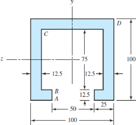
For each section illustrated, find the second moment of area, the location of the neutral axis, and the distances from the neutral axis to the top and bottom surfaces. Consider that the section is transmitting a positive bending moment about the z axis. Mz, where Mz = 10 kip · in if the dimensions of the section are given in ips units, or Mz = 1.13 kN · m if the dimensions are in SI units. Determine the resulting stresses at the top and bottom surfaces and at every abrupt change in the cross section.
Problem 3–34
(a) 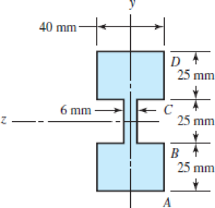
(b) 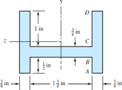
(c) Dimensions in mm
(d) 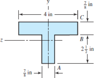
(a)
The second moment of area of the section.
The distance from the neutral axis to the top surfaces.
The distance from the neutral axis to the bottom surfaces.
The resulting stress at the top surface.
The resulting stress at the bottom surface.
The resulting stress at the abrupt change in cross-section.
Answer to Problem 34P
The second moment of area of the section is
The distance from the neutral axis to the top surface is
The distance from the neutral axis to the bottom surface is
The resulting stress at the top surface is
The resulting stress at the bottom surface is
The resulting stress at the abrupt change in cross-section is
Explanation of Solution
Figure-(1) shows two different sections divided of the in the same diagram.
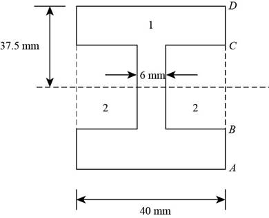
Figure-(1)
Calculate the second moment of area of the section.
Here, the second moment area of the area
Write the moment of inertia of the rectangular section.
Calculate the location of the neutral axis.
Calculate the location of the neutral axis.
Here, the area of the each section is
Write the resulting bending stress on beam.
Here, the distance from the neutral axis to the top or bottom surface is
Conclusion:
Substitute
Substitute
Substitute
Thus, the second moment of area of the section is
Substitute
Since the section is symmetrical about
Thus, the distance from the neutral axis to the top surface is
Thus, the distance from the neutral axis to the bottom surface is
Substitute
Since top and bottom surfaces are at the same distance from the neutral axis so the resulting stresses are same.
Thus, the resulting stress at the top surface is
Thus, the resulting stress at the bottom surface is
Substitute
Thus the resulting stress at the abrupt change in cross-section is
(b)
The second moment of area of the section.
The distance from the neutral axis to the top surface.
The distance from the neutral axis to the bottom surface.
The resulting stress at the point A.
The resulting stress at the point D.
The resulting stress at the abrupt change in cross-section at a point B.
The resulting stress at the abrupt change in cross-section at a point C.
Answer to Problem 34P
The second moment of area of the section is
The distance from the neutral axis to the top surface is
The distance from the neutral axis to the bottom surface is
The resulting stress at the point A is
The resulting stress at the point C is
The resulting stress at the abrupt change in cross-section at a point B is
The resulting stress at the abrupt change in cross-section at a point C is
Explanation of Solution
Figure-(2) shows two different sections divided of the in the same diagram.
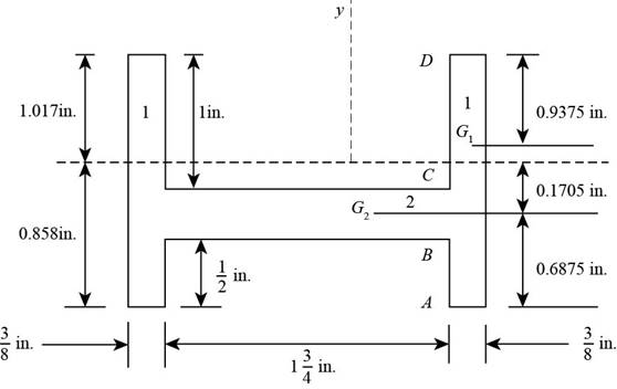
Figure-(2)
Write the expression for the area of section 1.
Here, the width of the section 1 is
Write the expression for the area of section 2.
Here, the width of the section 2 is
Calculate the location of the neutral axis.
Calculate the location of the neutral axis.
Here, the area of the each section is
Write the expression for the moment of inertia of section 1.
Write the expression for the moment of inertia of section 2.
Write the expression for the total moment of inertia.
Here, the distance of the neutral axis from the centroid of section 1 is
Write the resulting bending stress on beam.
Here, the distance from the neutral axis to the top or bottom surface is
Conclusion:
Substitute
Substitute
Substitute
Substitute
Substitute
Since the section is symmetrical about
Thus, the distance from the neutral axis to the top surface is
Thus, the distance from the neutral axis to the bottom surface is
Substitute
Substitute
Distance of the neutral axis from the two different centroids is
Substitute
Thus, the second moment of area of the section is
Substitute
Thus, the resulting stress at the bottom surface at a point A is
Substitute
Thus, the resulting stress at the point B is
Substitute
Thus, the resulting stress at the a point C is
Substitute
Thus, the resulting stress at the a point D is
(c)
The second moment of area of the section.
The distance from the neutral axis to the top surface.
The distance from the neutral axis to the bottom surface.
The resulting stress at the point A.
The resulting stress at the point D.
The resulting stress at the abrupt change in cross-section at a point B.
The resulting stress at the abrupt change in cross-section at a point C.
Answer to Problem 34P
The second moment of area of the section is
The distance from the neutral axis to the top surface is
The distance from the neutral axis to the bottom surface is
The resulting stress at the point A is
The resulting stress at the point D is
The resulting stress at the abrupt change in cross-section at a point B is
The resulting stress at the abrupt change in cross-section at a point C is
Explanation of Solution
Figure-(3) shows three different sections divided of the section in the same diagram.
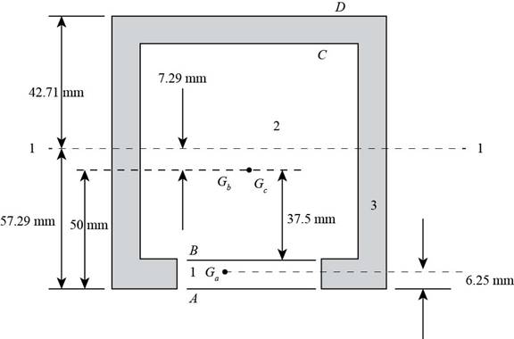
Figure-(3)
Write the expression for the area of section 1.
Here, the width of the section 1 is
Write the expression for the area of section 2.
Here, the width of the section 2 is
Write the expression for the area of section 3.
Here, the width of the section 3 is
Calculate the location of the neutral axis.
Calculate the location of the neutral axis.
Here, the area of the each section is
Write the expression for the moment of inertia of section 1.
Write the expression for the moment of inertia of section 2.
Write the expression for the moment of inertia of section 3.
Write the expression for the total moment of inertia.
Here, the distance of the neutral axis from the centroid of section 1 is
Write the resulting bending stress on beam.
Here, the distance from the neutral axis to the top or bottom surface is
Conclusion:
Substitute
Substitute
Substitute
Substitute
Substitute
Substitute
Substitute
Since the section is symmetrical about
Thus, the distance from the neutral axis to the top surface is
Thus, the distance from the neutral axis to the bottom surface is
Substitute
Substitute
Substitute
Distance of the neutral axis from the three different centroids of section is
Substitute
Thus, the second moment of area of the section is
Substitute
Thus, the resulting stress at the bottom surface at a point A is
Substitute
Thus, the resulting stress at the point B is
Substitute
Thus, the resulting stress at the a point C is
Substitute
Thus, the resulting stress at the a point D is
(d)
The second moment of area of the section.
The distance from the neutral axis to the top surface.
The distance from the neutral axis to the bottom surface.
The resulting stress at the point A.
The resulting stress at the point D.
The resulting stress at the abrupt change in cross-section at a point B.
Answer to Problem 34P
The second moment of area of the section is
The distance from the neutral axis to the top surface is
The distance from the neutral axis to the bottom surface is
The resulting stress at the point A is
The resulting stress at the point C is
The resulting stress at the abrupt change in cross-section at a point B is
Explanation of Solution
Figure-(4) shows two different sections divided of the section shown in the same diagram.
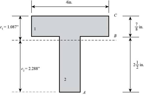
Figure-(4)
Write the expression for the area of section 1.
Here, the width of the section 1 is
Write the expression for the area of section 2.
Here, the width of the section 2 is
Calculate the location of the neutral axis.
Calculate the location of the neutral axis.
Here, the area of the each section is
Write the expression for the moment of inertia of section 1.
Write the expression for the moment of inertia of section 2.
Write the expression for the total moment of inertia.
Here, the distance of the neutral axis from the centroid of section 1 is
Write the resulting bending stress on beam.
Here, the distance from the neutral axis to the top or bottom surface is
Conclusion:
Substitute
Substitute
Substitute
Substitute
Substitute
Since the section is symmetrical about
Thus, the distance from the neutral axis to the top surface is
Thus, the distance from the neutral axis to the bottom surface is
Substitute
Substitute
Distance of the neutral axis from the two different centroids is
Substitute
Thus, the second moment of area of the section is
Substitute
Thus, the resulting stress at the bottom surface at a point A is
Substitute
Thus, the resulting stress at the point B is
Substitute
Thus, the resulting stress at the a point C is
Want to see more full solutions like this?
Chapter 3 Solutions
Shigley's Mechanical Engineering Design (McGraw-Hill Series in Mechanical Engineering)
Additional Engineering Textbook Solutions
Machine Elements in Mechanical Design (6th Edition) (What's New in Trades & Technology)
Statics and Mechanics of Materials (5th Edition)
Fundamentals of Aerodynamics
Vector Mechanics for Engineers: Statics
Thinking Like an Engineer: An Active Learning Approach (4th Edition)
Vector Mechanics for Engineers: Statics and Dynamics


- Find the stresses acting on the element rotated by ø= 50° from the x-axis. Here, each ø is positive in the counterclockwise direction. Plot these stresses on the plot of the element rotated by each ø.arrow_forwardDetermine the value of Qof the Transverse Shear Stress formula [T = (VQ)/(It)] at point p in mm3 for the triangular section shown in Figure 5.2d. Given h = 240 mm, B = 170 mm and y = 120 mm. h y - Barrow_forwardDetermine the absolute maximum shear stress of the stress state acting on the element shown in the following figure. y 40 Mpaarrow_forward
- The state of stress at a point in a machine component is given by ox = 120 MPa, oy = 55 MPa, Oz = -85 MPa, Oxy = -55 MPa, Oxz = -75 MPa, and oyz = 33 MPa. Construct the Mohr's circles of stress for this stress state and find the maximum shear stress.arrow_forwardThe book is subjected to the force of 60 lb Determine the state of stress at point A at section a-a. The cross section is circular and has a diameter of 0.5 in. Use the curved-beam formula to compute the bending stress (Figure 1) Figure 1.5 in. 13 45° B 1 of 1 > ▾ Part A Determine the normal stress. Express your answer using three significant figures and include the appropriate units. Enter negative value in the case of compression and positive value in the case of tension. g= Value Submit Part B ← A psi Previous Answers Request Answer X Incorrect; Try Again; 4 attempts remaining ✓ Correct < Return to Assignment Ċ 129 ? Determine the shear stress Express your answer using three significant figures and include the appropriate units. T= 0 psi Previous Answers Provide Feedbackarrow_forwardThe dimensions of the beam with the cross-section are given as b, a, t as in the figure on the right. The section is under the influence of the eccentric pressure force P. By constructing the equation of the neutral axis for this loading caseCalculate the largest and smallest stresses that will occur in the section and show the normal stress distribution on the section. P kN=85 a (mm)=120 b (mm)=150 t (mm)=40arrow_forward
- From the stress states given, draw the 3D Mohr's circle (lable the principle normal stresses, maximum and absolute shear stresses), and sketch the principle and shear planes. σxx = 70 ksi, σzz = -50 ksi, ?xy = 50 ksi (counterclockwise)arrow_forwardDetermine the shear stress in section AB and the angle oftorsion of point A in relation to point C. Diameters indicated in the figure and G = 39 GPaarrow_forwardFor the shaft shown below, determine the normal and shear stresses acting on the element located at point A, including stress concentrations. Then draw the stress element at A with the applied stresses and determine the three principal stress (0₁, 2 and, σ3) using Mohr's circle. r = 0.0042 m, d = 0.03 m, D = 0.033 m, T = 250 Nm P = 1500 N, M = 300 Nm, A M M DEHRƏC T d T P P rarrow_forward
- Homework :-in the figure shown. Find the total deformation and the stress in each section if E is 2.10° N/mm?. Ø=30mm Ø=20mm Ø=32.5mm 2 40 KN 1 40 KN 18cm 26сm 16cmarrow_forwardA stress element in a rock mass making up a slope experiences a 2D stress as follows: σx = 8 MPa, σy = 4 MPa , tauxy = 3 MPa A. By using the stress transformation equation, draw a curve of the stress variation experienced by the stress element at the axis of rotation angle θ = 0-180°. Use the interval θ = 1°, with the x-axis and stress as the y-axis. Mark on the curve where the principal stress and maximum shear stress occur. Draw the three stress curves completely and neatly B. Draw the stress element along with the magnitude and direction of the stress at the angle where the principal stress occurs and at the angle where the maximum shear stress occurs. C. Write down the direction vectors of the orientation of the principal stress (n1, and n₂) and the maximum shear stress (nmax). Write it in unit vector form i and j. D. Prove that the value of the stress invariant (I1, and I2) using the principal stress is reached and prove that the orthogonality condition of the direction cosine is…arrow_forwardDetermine the maximum tensile and compressive stresses in portion BC of the beam, under loading conditions of two vertical forces that applied on it. The beam has cross section as shown in figure. 100KN | 100KN 200 mm 25 mm 25 mm 150 um 25 mm 1500 mm 500 mm 500 mm 100 mmarrow_forward
 Elements Of ElectromagneticsMechanical EngineeringISBN:9780190698614Author:Sadiku, Matthew N. O.Publisher:Oxford University Press
 Mechanics of Materials (10th Edition)Mechanical EngineeringISBN:9780134319650Author:Russell C. HibbelerPublisher:PEARSON
 Thermodynamics: An Engineering ApproachMechanical EngineeringISBN:9781259822674Author:Yunus A. Cengel Dr., Michael A. BolesPublisher:McGraw-Hill Education
 Control Systems EngineeringMechanical EngineeringISBN:9781118170519Author:Norman S. NisePublisher:WILEY
 Mechanics of Materials (MindTap Course List)Mechanical EngineeringISBN:9781337093347Author:Barry J. Goodno, James M. GerePublisher:Cengage Learning
 Engineering Mechanics: StaticsMechanical EngineeringISBN:9781118807330Author:James L. Meriam, L. G. Kraige, J. N. BoltonPublisher:WILEY