
Concept explainers
Videos
Repeat Prob. 3–15 for:
(a) σx = 28 MPa, σy = 7 MPa, τxy = 6 MPa cw
(b) σx = 9 MPa, σy = –6 MPa, τxy = 3 MPa cw
(c) σx = –4 MPa, σy = 12 MPa, τxy = 7 MPa ccw
(d) σx = 6 MPa, σy = –5 MPa, τxy = 8 MPa ccw
(a)
The principle normal stress.
The shear stress.
The angle from
Answer to Problem 16P
The principle normal stress
The shear stress is
The angle from
Explanation of Solution
Write the coordinates of the points through which the Mohr’s circle pass.
Here, the stress along x face is
Draw the
Write the formula for the center point.
Here, the center point is
Write the expression for the angle between the line joining points A and B with
Here, the angle made by the diameter with positive x-axis in the counterclockwise direction is
Write the expression of the radius of circle.
Write the expression maximum in plane normal stress.
Here, the maximum in plane normal stress are
Write the expression of maximum in plane shear stress.
Here, the maximum shear stress is
Write the expression for the angle of maximum shear plane.
Here, the angle is
Conclusion:
Substitute the value
Draw the Mohr’s circle diagram.
The Figure (1) shows the Mohr’s circle diagram.
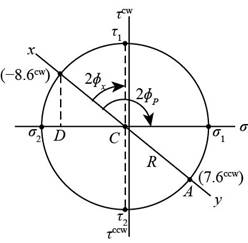
Figure (1)
Substitute the value
Substitute the value
Thus, the angle from
Substitute the value
Substitute the value
Thus, the principle normal stress
Substitute the value
Thus, the principle normal stress
Substitute the value
Thus, the shear stress is
Substitute the value
The Figure (2) shows the maximum in plane normal stress distribution about the plane.
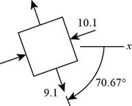
Figure (2)
The Figure (3) shows stress distribution at maximum shear stress plane.
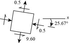
Figure (3)
(b)
The principle normal stress.
The shear stress.
The angle from
Answer to Problem 16P
The principle normal stress
The shear stress is
The angle from
Explanation of Solution
Write the coordinates of the points through which the Mohr’s circle pass.
Draw the
Write the formula for the center point.
Write the expression for the angle between the line joining points A and B with
Write the expression of the radius of circle.
Write the expression maximum in plane normal stress.
Write the expression of maximum in plane shear stress.
Write the expression for the angle of maximum shear plane.
Write the expression for the angle between the line joining points A and B with
Conclusion:
Substitute
Substitute
Draw the Mohr’s circle diagram.
The Figure (4) shows the Mohr’s circle diagram.
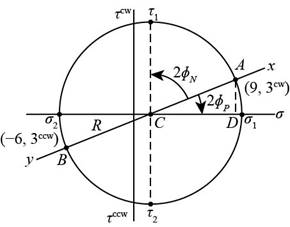
Figure (4)
Substitute the value
Substitute the value
Thus, the angle from
Substitute the value
Substitute
Thus, the principle normal stress
Substitute
Thus, the principle normal stress
Substitute the value
Thus, the shear stress is
Substitute the value
The Figure (5) shows the maximum in plane normal stress distribution about the plane.
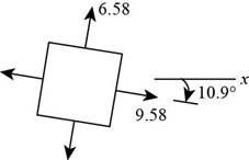
Figure (5)
The Figure (6) shows stress distribution at maximum shear stress plane.
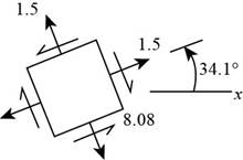
Figure (6)
Thus, the principle normal stress
(c)
The principle normal stress.
The shear stress.
The angle from
Answer to Problem 16P
The principle normal stress
The shear stress is
The angle from
Explanation of Solution
Write the coordinates of the points through which the Mohr’s circle pass.
Draw the
Write the formula for the center point.
Write the expression for the angle between the line joining points A and B with
Write the expression of the radius of circle.
Write the expression maximum in plane normal stress.
Write the expression of maximum in plane shear stress.
Write the expression for the angle of maximum shear plane.
Conclusion:
Substitute the value
Substitute
Draw the Mohr’s circle diagram.
Figure (7) shows the Mohr’s circle diagram.
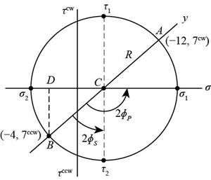
Figure (7)
Substitute the value
Substitute the value
Substitute the value
Substitute the value
Substitute the value
Substitute the value
Substitute the value
The Figure (8) shows the maximum in plane normal stress distribution about the plane.
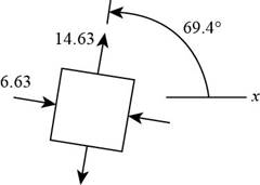
Figure (8)
The Figure (9) shows stress distribution at maximum shear stress plane.
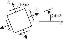
Figure (9)
Thus, the he principle normal stress
(d)
The principle normal stress.
The shear stress.
The angle from
Answer to Problem 16P
The principle normal stress
The shear stress is
The angle from
Explanation of Solution
Write the coordinates of the points through which the Mohr’s circle pass.
Draw the
Write the formula for the center point.
Write the expression for the angle between the line joining points A and B with
Write the expression of the radius of circle.
Write the expression maximum in plane normal stress.
Write the expression of maximum in plane shear stress.
Write the expression for the angle of maximum shear plane.
Write the expression for the angle between the line joining points A and B with
Conclusion:
Substitute
Substitute
Draw the Mohr’s circle diagram.
The Figure (10) shows the Mohr’s circle diagram.
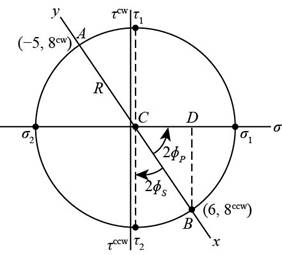
Figure (10)
Substitute the value
Substitute the value
Substitute the value
Substitute the value
Substitute the value
Substitute the value
Substitute the value
The Figure (11) shows the maximum in plane normal stress distribution about the plane.
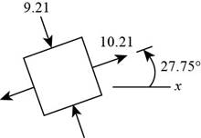
Figure (11)
The Figure (12) shows stress distribution at maximum shear stress plane.
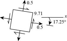
Figure (12)
Thus, the principle normal stress
Want to see more full solutions like this?
Chapter 3 Solutions
Shigley's Mechanical Engineering Design (McGraw-Hill Series in Mechanical Engineering)


- A round bar ABC of length 2L (see figure) rotates about an axis through the midpoint C with constant angular speed w (radians per second). The material of the bar has weight density y. (a) Derive a formula for the tensile stress a’ in the bar as a function of the distance x from the midpoint C. (b) What is the maximum tensile stress a max?arrow_forwardSolve the preceding problem for a W 200 × 41,7 shape with h = 166 mm, h = 205 mm. rw = 7.24 mm, tE= ILS mm,andV = 38 kN.arrow_forwardA vertical pole of solid, circular cross section is twisted by horizontal forces P = 5kN acting at the ends of a rigid horizontal arm AB (see figure part a). The distance from the outside of the pole to the line of action of each force is c = 125 mm (sec figure part b) and the pole height L = 350 mm. (a) If the allowable shear stress in the pole is 30 MPa, what is the minimum required diameter dminof the pole? (b) What is the torsional stiffness of the pole (kN · m/rad)? Assume that G = 28 GPa. (c) If two translation al springs, each with stiffness k =2550 kN/m, are added at 2c/5 from A and B (see figure part c), repeat part (a) to find dmin. Hint: Consider the pole and pair of springs as "springs in parallel."arrow_forward
- A solid circular bar of steel (G = 78 GPa) transmits a torque T = 360 N - m. The allowable stresses in tension, compression, and shear arc 90 MPa, 70 MPa, and 40 MPa, respectively. Also, the allowable tensile strain is 220 x 10-6, Determine the minimum required diameter d of the bar, If the bar diameter d = 40 mm, what is Tmax?arrow_forward-11 A solid steel bar (G = 11.8 X 10⁶ psi ) of diameter d = 2,0 in. is subjected to torques T = 8.0 kip-in. acting in the directions shown in the figure. Determine the maximum shear, tensile, and compressive stresses in the bar and show these stresses on sketches of properly oriented stress elements. Determine the corresponding maximum strains (shear, tensile, and compressive) in the bar and show these strains on sketches of the deformed elements.arrow_forwardAn aluminum tube has inside diameter dx= 50 mm, shear modulus of elasticity G = 27 GPa, v = 0.33, and torque T = 4.0 kN · m. The allowable shear stress in the aluminum is 50 MPa, and the allowable normal strain is 900 X 10-6. Determine the required outside diameter d2 Re-compute the required outside diameter d2, if allowable normal stress is 62 MPa and allowable shear strain is 1.7 X 10-3.arrow_forward
- Repeat the preceding problem using sx= 5.5 MPa. ??y= 4 MPa. and txy= 3.2 MPa.arrow_forwardSolve the preceding problem for the following data: diameter LO m, thickness 48 mm, pressure 22 MPa, modulus 210 GPa. and Poisson's ratio 0.29arrow_forwardThe stresses acting on a stress element on the arm of a power excavator (see figure) are ax= 52 MPa and txy= 33 MPa (sec figure). What is the allowable range of values for the stress if the maximum shear stress is limited to = 37 MPa?arrow_forward
- Solve the preceding problem for the following data: b = 6 in., b = 10 in, L = 110 ft, tan a = 1/3, and q = 325 lb/ft.arrow_forwardA tubular shaft being designed for use on a construction site must transmit 120 kW at 1,75 Hz, The inside diameter of the shaft is to be one-half of the outside diameter. If the allowable shear stress in the shaft is 45 MPa, what is the minimum required outside diameter d?arrow_forwardA bar ABC revolves in a horizontal plane about a vertical axis at the midpoint C (see figure). The bar, which has a length 2L and crass-sectional area A, revolves at constant angular speed at. Each half of the bar (AC and BC) has a weight W, and supports a weight W2at its end. Derive the following formula for the elongation of one-half of the bar (that is. the elongation of either AC ar BC). =L223gEA(w1+3w2) in which E is t he modulus of elasticity of the material of the bar and g is the acceleration of gravity.arrow_forward
 Mechanics of Materials (MindTap Course List)Mechanical EngineeringISBN:9781337093347Author:Barry J. Goodno, James M. GerePublisher:Cengage Learning