
Videos
Assume that the two circuits in Fig. 19.135 are equivalent. The parameters of the two circuits must be equal. Using this factor and the z parameters, derive Eqs. (9.67) and (9.68).
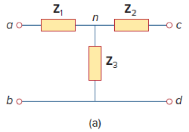
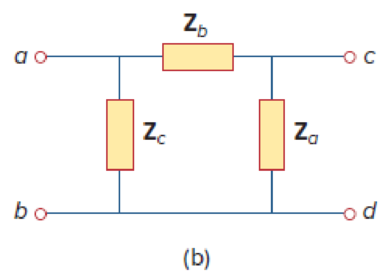
Figure 19.135
Derive the expressions in Equations (9.67) and (9.68) in the textbook.
Explanation of Solution
Given Data:
Refer to Figure 19.135 in the textbook given circuits.
Consider the parameters of two circuits are equal.
Calculation:
Refer to Figure 19.135 (a) in the textbook and write the expression for
Refer to Figure 19.135 (b) in the textbook and write the expression for
From Equation (1), substitute
Refer to Figure 19.135 (a) in the textbook and write the expression for
Refer to Figure 19.135 (b) in the textbook and write the expression for
From Equation (3), substitute
Refer to Figure 19.135 (a) in the textbook and write the expression for
Refer to Figure 19.135 (b) in the textbook and write the expression for
From Equation (5), substitute
Subtract Equation (4) from Equation (2) and obtain the expression as follows:
Add Equations (6) and (7) and obtain the expression as follows:
Simplify the expression as follows:
Subtract Equation (8) from Equation (6) and obtain the expression as follows:
Subtract Equation (8) from Equation (2) and obtain the expression as follows:
From Equations (8), (9), and (10), the expressions in Equation (9.68) are derived.
Note that, the obtained expressions are not same as the expressions in the textbook, since the position of the impedances are changed in the given circuits.
Use expressions in Equations (8), (9), and (10) and obtain the expression as follows:
Divide Equation (11) by Equation (8) and obtain the expression as follows:
Divide Equation (11) by Equation (9) and obtain the expression as follows:
Divide Equation (11) by Equation (10) and obtain the expression as follows:
From Equations (12), (13), and (14), the expressions in Equation (9.67) are derived.
Note that, the obtained expressions are not same as the expressions in the textbook, since the position of the impedances are changed in the given circuits.
Conclusion:
Thus, the expressions in Equations (9.67) and (9.68) in the textbook are derived.
Want to see more full solutions like this?
Chapter 19 Solutions
Fundamentals of Electric Circuits


- 10 For he circuit shown in the figure below, find Z- * ?Parameters 100 80 120 V1 160 V2 21.21 ohm, 19.19 ohm, 23.86 ohm 21.19 ohm, 19.86 ohm, 23.21 ohm O 21.86 ohm, 19.19 ohm, 23.21 ohm O 21.86 ohm, 19.21 ohm, 23.19 ohm Oarrow_forwardPractice Problem 19.6 h = 2 kΩ h12 = 104 h₂1 = 100 h22 = 10-5 S Zin Figure 19.27 For Practice Prob. 19.6. www 50 ΚΩ Find the impedance at the input port of the circuit in Fig. 19.27. Answer: 1.6667 kN.arrow_forwardPractice Problem 19.6 Find the impedance at the input port of the circuit in Fig. 19.27. Answer: 1.6667 kN. h1 = 2 k2 h12 = 104 h21 = 100 h2 = 10-5 s 50 k2 %3D Zin Figure 19.27 For Practice Prob. 19.6.arrow_forward
- Find the Y-parameters of the circuit below j20 V, 40 0.4V2 3Varrow_forwardObtain the parameters h12 and g12arrow_forwardFor he circuit shown in the figure below, find Z-Parameters? * 100 ww 8Ω 120 I, ww 160 ww + + V1 V2 O 21.21 ohm, 19.19 ohm, 23.86 ohm O 21.19 ohm, 19.86 ohm, 23.21 ohm 21.86 ohm, 19.19 ohm, 23.21 ohm O 21.86 ohm, 19.21 ohm, 23.19 ohmarrow_forward
- 3. Fined RT for the circuit shown below 101 31 201 VT 19. 51 10 Varrow_forwardChapter 19, Problem 4. Caiculate the : parameters for the circuit in Fig. 19.68. Figure 19.68arrow_forwardTwo 2-port networks with following parameters are connected in series. Z parameters of network - 5 6 - 1 92 Y - parameters of network – 2 [95] 7 4 The z-parameters of series combination network isarrow_forward
- Find the Y - parameters of the circuit below 30 0 15 Q 10 Qarrow_forwardIn the parallel connection of the following two port network, which of the following is correct he Vla 1₁ V₁b Y11 Y11a / Y11b Y11=Y11a + Y11b Y11=Y11a x Y11b O Y11=Y11a - Y11b Y Y₂ V₂0 126 √₂b- * Studying of transient is important to Take in consideration the abnormal cases which might damage the components Take in consideration the stable cases so that to deal well with the system Take in consideration the steady state case Take in consideration the components positionsarrow_forwardFind the à parameters of the nerwork in Fig. 19.49. Example 19.15 Solution: From Eq (19.16), 612 ww 10 2 10 2 showing that h,, and h, can be found by setting V, = 0. Also by setting I = 1 A, h becomes V/1 while h2: becomes I2/1. With this in mind we draw the schematic in Fig. 19.50(a). We insert a 1-A dc current source Figure 19.49 For Example 19.15.arrow_forward
 Introductory Circuit Analysis (13th Edition)Electrical EngineeringISBN:9780133923605Author:Robert L. BoylestadPublisher:PEARSON
 Delmar's Standard Textbook Of ElectricityElectrical EngineeringISBN:9781337900348Author:Stephen L. HermanPublisher:Cengage Learning
 Programmable Logic ControllersElectrical EngineeringISBN:9780073373843Author:Frank D. PetruzellaPublisher:McGraw-Hill Education
 Fundamentals of Electric CircuitsElectrical EngineeringISBN:9780078028229Author:Charles K Alexander, Matthew SadikuPublisher:McGraw-Hill Education
 Electric Circuits. (11th Edition)Electrical EngineeringISBN:9780134746968Author:James W. Nilsson, Susan RiedelPublisher:PEARSON
 Engineering ElectromagneticsElectrical EngineeringISBN:9780078028151Author:Hayt, William H. (william Hart), Jr, BUCK, John A.Publisher:Mcgraw-hill Education,