
Concept explainers
Videos
The circuit in Fig. 19.116 may be regarded as two two-ports connected in parallel. Obtain the y parameters as functions of s.
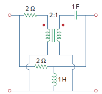
Figure 19.116
Find the admittance parameters for the given two-port network in Figure 19.116 in the textbook.
Answer to Problem 69P
The admittance parameters for the given two-port network are
Explanation of Solution
Given Data:
Refer to Figure 19.116 in the textbook for the given two-port network.
Formula used:
Write the expressions for admittance parameters of a two-port network as follows:
Calculation:
Note that the dimensions are neglected for simple calculations.
Consider upper network as network
As the interconnection network is a parallel combination of two networks, it is easier to obtain the required objective in terms of admittance parameters. Find the admittance parameters for upper and lower network and add them to obtain the overall admittance parameters.
The admittance parameters
Redraw the upper network by short circuiting the port-2 as shown in Figure 1.
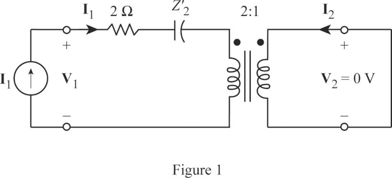
Write the expression for equivalent impedance of secondary winding capacitance when the transformer is referred to the primary winding as follows:
Here,
Substitute
From Figure 1, write the expression for
Substitute
Rearrange the expression as follows:
Substitute
From Figure 1, write the expression for
From Equation (6), substitute
Rearrange the expression as follows:
Substitute
The admittance parameters
Redraw the given two-port network by short circuiting the port-1 as shown in Figure 2.
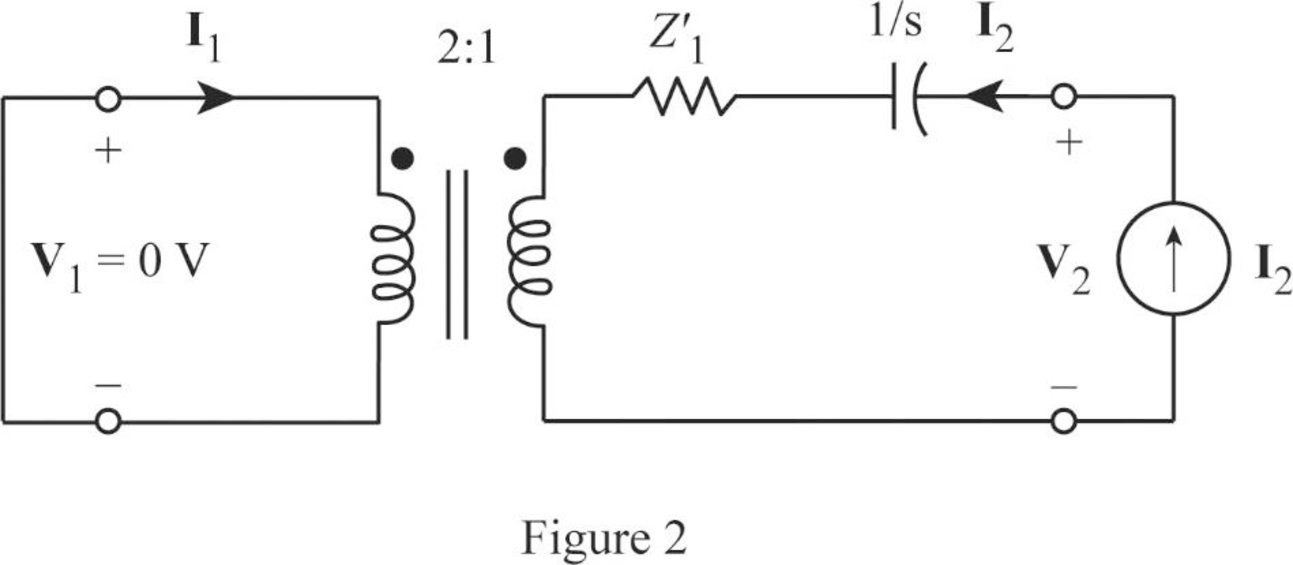
Write the expression for equivalent impedance of primary winding resistance when the transformer is referred to the secondary winding as follows:
Here,
Substitute
From Figure2, write the expression for
Substitute 0.5 for
Rearrange the expression as follows:
Substitute
From Figure 1, write the expression for
From Equation (10), substitute
Rearrange the expression as follows:
Substitute
From the calculations, write the y-parameters for upper network as follows:
Redraw the lower network by short circuiting the port-2 as shown in Figure 3.
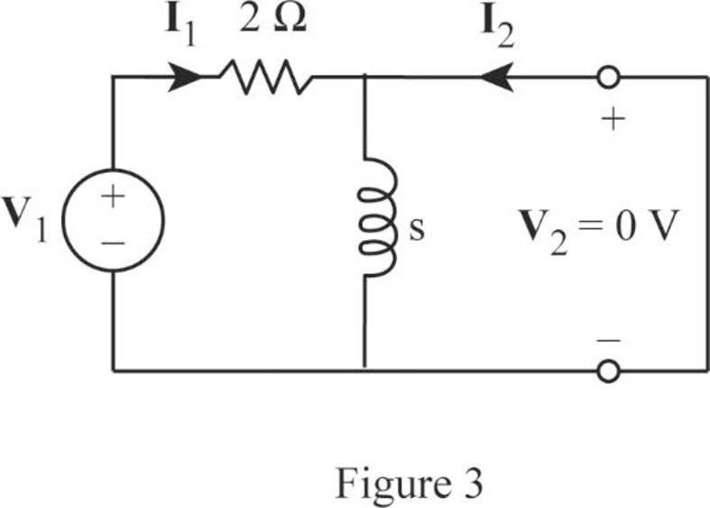
As the current bypasses through the short circuit path, redraw the circuit in Figure 3 as shown in Figure 4.
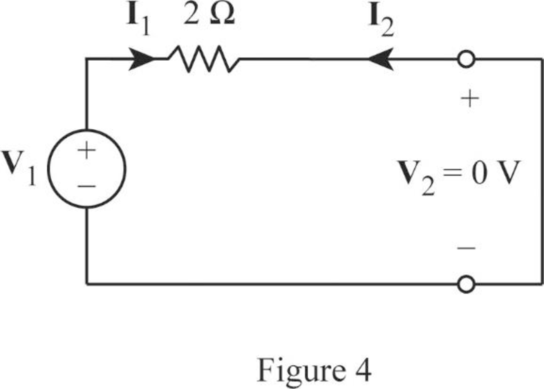
From Figure 4, write the expression for
Rearrange the expression as follows:
Substitute 0.5 for
From Figure 1, the expression for current
From Equation (11), substitute
Rearrange the expression as follows:
Substitute
Redraw the lower network by short circuiting the port-1 as shown in Figure 5.
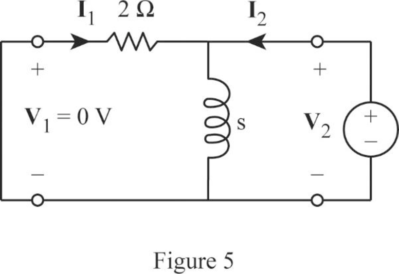
From Figure 5, write the expression for
Rearrange the expression as follows:
Substitute
From Figure 5, obtain the current
From Equation (12), substitute
Rearrange the expression as follows:
Substitute
From the calculations, write the y-parameters for lower network as follows:
As the upper and lower networks are connected in parallel, write the expression for overall admittance parameters as follows:
Substitute
Simplify the expression as follows:
Conclusion:
Thus, the admittance parameters for the given two-port network are
Want to see more full solutions like this?
Chapter 19 Solutions
Fundamentals of Electric Circuits


- Obtain the z parameters for the network in Fig. 19.69 as functions of s. IH 王 wwarrow_forwardPractice Problem 19.6 Find the impedance at the input port of the cicuit in Fig. 19.27. Answer: 1.6667 kfl. b =2 ka = 10 b = 100 = 10s 30 ka Figure 19.27 For Practice Prob. 19.6.arrow_forwardPractice Problem 19.6 Find the impedance at the imput port of the circuit in Fig. 19.27. =2 k Answer: 1.6667 kl. = 100 b= 10s 50 ka Figure 19.27 For Practice Prob. 19.6. rircut in F: 19.28arrow_forward
- 19.20 Find the y parameters for the circuit in Fig. 19.81. 3i, 2Ω 4Ω 6Ω Figure 19.81 For Prob. 19.20.arrow_forwardAi, 62 Find the h parameters of the network in Fig. 19.49. 10 2arrow_forwardPractice Problem 19.6 h = 2 kΩ h12 = 104 h₂1 = 100 h22 = 10-5 S Zin Figure 19.27 For Practice Prob. 19.6. www 50 ΚΩ Find the impedance at the input port of the circuit in Fig. 19.27. Answer: 1.6667 kN.arrow_forward
- Derive the expressions for the g parameters as functions of the zparameters.arrow_forwardFind The Impedance At The Input Port of the circuit in Fig. 19.27arrow_forwardFind the parameters of the two-port network in Fig. 19.9. Practice Problem 19.1 ANswer: z, = 28 N, z,2 = Z = z = 12 2 16a ww- 122 Figure 19.9 For Practice Prob. 19.1.arrow_forward
- For the ladder nerwork in Fig. 19.30, determine the g parameters in the s domain. Practice Problem 19.7 +2 +3: +1 +3s +1 Answer: [g) 5(: + 2) + 3s +1 +3s+1 Figure 19.30 For Practice Prob. 19.7.arrow_forwardCalculate I, and I2 in the two-port of Fig. 19.11. I 2Ω Z11 = 6 Q Z12 = -j4 Q Z21 = -j4 Q Z22 = 8 Q + 2/30° V (± V2 Figure 19.11 For Practice Prob. 19.2. Answer: 200/30° mA, 100/120° mA.arrow_forwardObtain the Y parameters of the two-port network shown in the figure below: 0.5V2 V2arrow_forward
 Introductory Circuit Analysis (13th Edition)Electrical EngineeringISBN:9780133923605Author:Robert L. BoylestadPublisher:PEARSON
 Delmar's Standard Textbook Of ElectricityElectrical EngineeringISBN:9781337900348Author:Stephen L. HermanPublisher:Cengage Learning
 Programmable Logic ControllersElectrical EngineeringISBN:9780073373843Author:Frank D. PetruzellaPublisher:McGraw-Hill Education
 Fundamentals of Electric CircuitsElectrical EngineeringISBN:9780078028229Author:Charles K Alexander, Matthew SadikuPublisher:McGraw-Hill Education
 Electric Circuits. (11th Edition)Electrical EngineeringISBN:9780134746968Author:James W. Nilsson, Susan RiedelPublisher:PEARSON
 Engineering ElectromagneticsElectrical EngineeringISBN:9780078028151Author:Hayt, William H. (william Hart), Jr, BUCK, John A.Publisher:Mcgraw-hill Education,