
Calculate the voltage gain, current gain, input impedance, and output impedance for the amplifier shown in Figure 19.131 in the textbook.
Answer to Problem 92P
The voltage gain, current gain, input impedance, and output impedance for the amplifier are
Explanation of Solution
Given Data:
Refer to Figure 19.131 in the textbook for the amplifier circuit.
From the given amplifier circuit, the internal resistance
Formula used:
Refer to Equation 19.73 in the textbook and write the expression for voltage gain of a amplifier in terms of hybrid parameters as follows:
Here,
Write the expression for current gain of the amplifier as follows:
Here,
Write the expression for input impedance of the amplifier as follows:
Calculation:
Redraw the given circuit as shown in Figure 1.
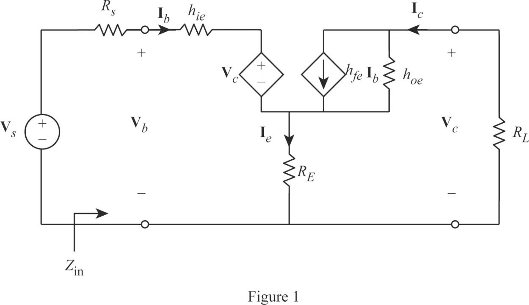
From Figure 1, write the expression for emitter current as follows:
Write the expression for base voltage from the circuit in Figure 1 as follows:
Write the expression for collector current as follows:
Write the expression for collector voltage as follows:
From Equation (7), substitute
Rearrange the expression as follows:
From Equation (2), substitute
Substitute 100 for
From Equation (6), substitute
Rearrange the expression as follows:
Rearrange the expression in Equation (5) as follows:
From Equations (7) and (9), substitute
Rearrange the expression as follows:
Substitute 100 for
Simplify the expression as follows:
From Equation (1), substitute
From Equation (9), substitute
Rearrange the expression as follows:
Substitute 100 for
From Equation (3), substitute
Consider output voltage
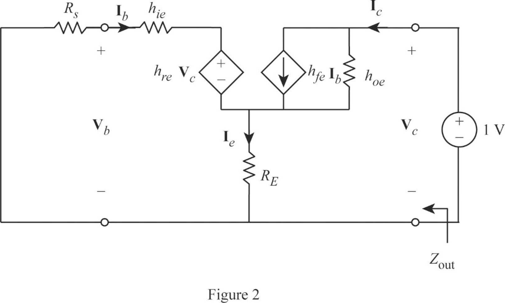
Apply KVL to the input loop for the circuit in Figure 2 as follows:
Substitute 1 for
Apply KCL at the output node for the circuit in Figure 2 as follows:
Substitute 1 for
Rearrange the expression as follows:
From Equation (12), substitute
Substitute 100 for
Write the expression for output impedance of the amplifier as follows:
Substitute 1 for
Conclusion:
Thus, the voltage gain, current gain, input impedance, and output impedance for the amplifier are
Want to see more full solutions like this?
Chapter 19 Solutions
Fundamentals of Electric Circuits

- Q/ An a.c bridge is in balance with the following constants : Arm AB , R=200 Q in series with C= 0.265 µF. Arm AC , R,=300 2. Arm CD , Unknown. Arm BD, C3= 0.79 µF. The oscillator frequency is 1kHz , supply voltage =lvolt between A and D points. Find: Zx and calculate its components ( R, L or C).arrow_forwardObtain the parameter H12arrow_forwardFor the system shown below, find Vo(s)/V(s)arrow_forward
- Find output signal vo(t) from the graph. 0.5 F cos (0.5t) v. (1) v. (1) -3A k Злarrow_forwardDetermine Z. Transfurim including reyina of Cunvergence Int Xcn)= )arrow_forwardA transistor is used as a switch and the waveforms are shown below. The parameters are given as follows: Vcc = 150 V, VBE(sat) = 5 V, Igs = 10 A, VCE(sat) = 2 V, Ics = 120 A, ta = 0.5 us, t, = 1 us, ts = 2 us, tf = 2 us and f =10 KHz, k = 50 % and ICEO = 1 mA. The conduction time t, and the blocking time t, are equal to: VCE Vcc VCE(s31) ton toff Ics ICEO ig Select one: O a. 46 µs, 48 us O b. 20 us, 45 µs O C. 48.5 us, 46 µs o d. 45 µs, 20 µsarrow_forward
- For the phase-shift oscillator, determine the feedback resistor required to produce an oscillator frequency of 7.2 kHz if all the resistors in the 3 RC networks are 12.5 kΩ.arrow_forward(b) Derive the transfer function for the electric system shown. Draw a schematic diagram of an analogous mechanical system. R -ww R2 C수arrow_forwardThe tuned collector oscillator circuit used in the local oscillator of a radio receiver makes use of an LC tuned circuit with L1 = 58.6 µH and C1 = 300 pF. Calculate the frequency of oscillations.arrow_forward
- If a 50 mV r.m.s. input signal is applied to the amplifier in Fig. 19.68, what is the peak-to-peak output voltage? Given that g„= 5000 µs. [920 mV] VDD + 12 V 1.5 kn R, C3 v out 10µF VinoHE 10 μF R,=10 k2 C2 I µF 10 M2 RG 1 kN ZRs Fig. 19.68arrow_forwardA system is using NRZ-I to transfer 6 Mbps of data. What should be the minimum bandwidth: A) 2000 KHz B 3000 KHz © 6000 KHz D) 1200 KHzarrow_forwardFor the phase-shift oscillator, determine the feedback resistor required to produce an ocillator frequency of 7.2 kHz if all the resistors in the 3 RC networks are 12.5 kQ. А 12.5 k2 В 4.17 kO C) 362.5 kN D) 125 k2arrow_forward
 Introductory Circuit Analysis (13th Edition)Electrical EngineeringISBN:9780133923605Author:Robert L. BoylestadPublisher:PEARSON
 Delmar's Standard Textbook Of ElectricityElectrical EngineeringISBN:9781337900348Author:Stephen L. HermanPublisher:Cengage Learning
 Programmable Logic ControllersElectrical EngineeringISBN:9780073373843Author:Frank D. PetruzellaPublisher:McGraw-Hill Education
 Fundamentals of Electric CircuitsElectrical EngineeringISBN:9780078028229Author:Charles K Alexander, Matthew SadikuPublisher:McGraw-Hill Education
 Electric Circuits. (11th Edition)Electrical EngineeringISBN:9780134746968Author:James W. Nilsson, Susan RiedelPublisher:PEARSON
 Engineering ElectromagneticsElectrical EngineeringISBN:9780078028151Author:Hayt, William H. (william Hart), Jr, BUCK, John A.Publisher:Mcgraw-hill Education,