
ANALYSIS+DESIGN OF LINEAR CIRCUITS(LL)
8th Edition
ISBN: 9781119235385
Author: Thomas
Publisher: WILEY
expand_more
expand_more
format_list_bulleted
Videos
Textbook Question
Chapter 1, Problem 1.24P
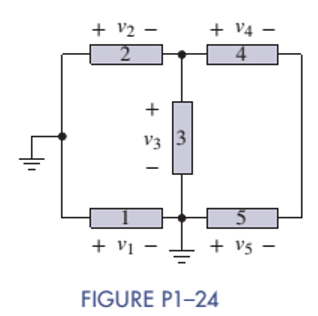
In Figure P1-24 the voltage
Expert Solution & Answer
Want to see the full answer?
Check out a sample textbook solution
Students have asked these similar questions
Draw the outputs Q1, Q2 AND X in
the system given in the figure
CLK-
CLK
D
Q1
Q2
X
U
O
a
Q1
Q2
HAL
LO
L1
MUX
SO
X
The diagram in the figure shows a simple circuit consisting of a battery and a load consisting of two resistors.The battery voltage is UB = 56 V and the value of the resistors is:R1 = 1800R2 = 5400a) The ammeters in the circuit show the following value:A1 shows valueA2 shows valueA3 shows valueb) In the load, the effect developsc) The total resistance of the load is
Each of the cells shown in the figure has an emf of 1.50 V and a 0.0750-ohm internalresistance. Find I1, I2, and I3.
Chapter 1 Solutions
ANALYSIS+DESIGN OF LINEAR CIRCUITS(LL)
Ch. 1 - Given an electrical quantity described in terms of...Ch. 1 - Express the following quantities to the nearest...Ch. 1 - An ampere-hour (Ah) meter measures the time...Ch. 1 - Electric power companies measure energy...Ch. 1 - Fill in the blanks in the following statements. To...Ch. 1 - Which of the two entries is larger? 1000...Ch. 1 - A wire carries a constant current of 30A. How many...Ch. 1 - The net positive charge flowing through a device...Ch. 1 - Figure P1-9 shows a plot of the net positive...Ch. 1 - The net negative charge flowing through a device...
Ch. 1 - A cell phone charger outputs 9.6 V and is...Ch. 1 - For 0t5s, the current through a device is...Ch. 1 - The charge flowing through a device is...Ch. 1 - The 12-V automobile battery in Figure P1-14 has an...Ch. 1 - The current through a device is zero for t0 and is...Ch. 1 - A string of holiday lights is protected by a 12A...Ch. 1 - When illuminated the relationship for a photocell...Ch. 1 - A new 6-V alkaline lantern battery delivers...Ch. 1 - The maximum current allowed by a device's power...Ch. 1 - Traffic lights are being converted from...Ch. 1 - Two electrical devices are connected as shown in...Ch. 1 - Figure P1-22 shows an electric circuit with a...Ch. 1 - Figure P1-22 shows an electric circuit with a...Ch. 1 - In Figure P1-24 the voltage v2 is 10 V and v4 is 5...Ch. 1 - For t0, the voltage across and power absorbed by a...Ch. 1 - Repeat Problem 1-22 using MATLAB to perform the...Ch. 1 - Using the passive sign convention, the voltage...Ch. 1 - Power Ratio (PR) in dB A stereo amplifier takes...Ch. 1 - AC to DC Converter A manufacturer's data sheet for...Ch. 1 - Charge-Storage Device A capacitor is a...Ch. 1 - Compute Data Sheet A manufacturer's data sheet for...Ch. 1 - Light Source Comparison A Today people have three...
Additional Engineering Textbook Solutions
Find more solutions based on key concepts
Consider the circuit shown in Figure P1.63. Find the current iR flowing through the resistor. Find the power fo...
Electrical Engineering: Principles & Applications (7th Edition)
The average plasma screen TV draws 339 W of power, whereas the average LCD TV draws 213 W. If each set was used...
Introductory Circuit Analysis (13th Edition)
The switch shown in Fig. P 7.4 has been open for a long time before closing at t = 0.
Figure P7.4
Find io(0−),...
Electric Circuits (10th Edition)
Find Io in the network in Fig. P5.55 using Nortons theorem.
Basic Engineering Circuit Analysis
The switch in the circuit shown has been closed for a long time and is opened at t = 0.
Calculate the initial v...
Electric Circuits. (11th Edition)
The switch in the bottom loop of Fig. P6.1 is closed at t = 0 and then opened at a later time t1. What is the d...
Fundamentals of Applied Electromagnetics (7th Edition)
Knowledge Booster


Learn more about
Need a deep-dive on the concept behind this application? Look no further. Learn more about this topic, electrical-engineering and related others by exploring similar questions and additional content below.Similar questions
- A dc generator and a battery are connected to a resistive load RL in the figure below. For each, determine the value of RL for maximum power transfer to RL. Next is to determine RL to 75% efficiencyarrow_forwardPlease solve this solve both parts plx solve on word this is about electric circuit subjectarrow_forwardA charger, a battery and a load are connected in parallel. The voltage across the charger is 12.5 volts and the battery has an emf of 12 volts and the internal resistance of 0.1 ohm. The load of 2 ohms resistor. Find the current through the charger.arrow_forward
- A charger , a battery and a load are connected in parallel. The voltage across the charger is 12.5 volts and the battery has an emf of 12 volts and internal resistance of 0.1 ohm. The load consists of a 2 ohms resistor. Find the current through the charger.arrow_forwardI did a physics lab and got some values. I want to check them theoretically to see how the results differ. From this diagram, answer the following questions: The laws to be verified included the conservation of current in a node, the addition of potentials for components in series, and the addition of currents for components in parallel. The data : R1: 1094 ohm R2 : 998 ohm R3: 1094 ohmR4: 25 ohm Source 1 : 5 V Source 2 : 1.5 Varrow_forwardKirchhoffs Law find all the currents through the resistors in milli Amperes and the voltage drops across all the resistors. Steps: a) redraw the circuit with the voltages and currents labeled for each of the respective resistors. b)solvearrow_forward
- Using NODAL VOLTAGE ANALYSIS, solve Vy and Vx and voltages across EACH RESISTOR. Put signs on each resistors in the figure and draw the flow of currentarrow_forwardIn the figure, A. What isthe current through R1? The current in R9? B. What is the voltage across R2? C. What is the voltage across R6?arrow_forwardWhat is the difference between the cut-off voltage VGS0 f and the narrowing voltage Vp? Explain this with the diagramarrow_forward
- Given n2 = 510, what is n₁? 5415° V 3060 85 1530 O 170 +21 000 ell n₁: N₂ + 30415° Varrow_forwardGiven four resistors R1 = 100 ohms, R2=250 ohms, R3 = 350 ohms, and R4 = 200 ohms such that R1 and R2 in parallel will be connected in series with R3 and R4 in parallel. The series-parallel combination is connected across a 24-volt DC power supply. Find the voltage across R2 and voltage across R4 voltage drops across R2 and R4 are both 12 V voltage drop across R2 is 18.63 V and voltage across R4 is 5.37 V voltage drop across R2 is 8.63 V and voltage across R4 is 15.37 V voltage drop across R2 is 8.63 V and voltage across R4 is 15.37 Varrow_forwardTwo batteries are connected in parallel delivering power to a power resistor. The first battery has an open circuit voltage of 12.6 V and an internal resistance of 0.2 ohm. The second battery has an open circuit voltage of 12.2 V and an internal resistance of 0.3 ohm. Find the maximum power delivered to the load resistance.arrow_forward
arrow_back_ios
SEE MORE QUESTIONS
arrow_forward_ios
Recommended textbooks for you
 Delmar's Standard Textbook Of ElectricityElectrical EngineeringISBN:9781337900348Author:Stephen L. HermanPublisher:Cengage Learning
Delmar's Standard Textbook Of Electricity
Electrical Engineering
ISBN:9781337900348
Author:Stephen L. Herman
Publisher:Cengage Learning
Lesson 2 - Source Transformations, Part 2 (Engineering Circuits); Author: Math and Science;https://www.youtube.com/watch?v=7gno74RhVGQ;License: Standard Youtube License