
Videos
The switch in the bottom loop of Fig. P6.1 is closed at t = 0 and then opened at a later time t1. What is the direction of the current I in the top loop (clockwise or counterclockwise) at each of these two times?
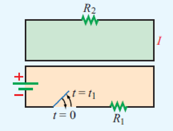
Figure P6.1 Loops of Problem 6.1.
The direction of the current
Answer to Problem 1P
The current in the top loop will be in counter-clockwise direction.
Explanation of Solution
Given data:
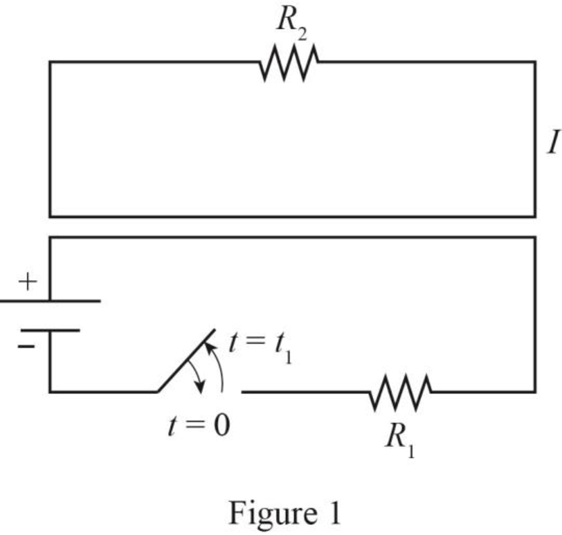
The required diagram is drawn as shown in Figure 1.
Calculation:
The required diagram is drawn as shown in Figure 2 at
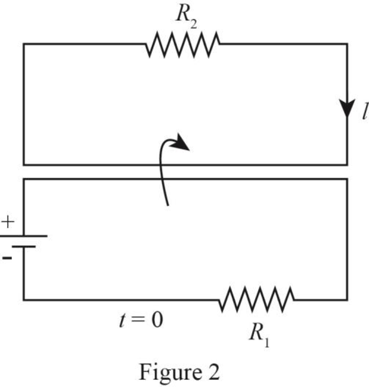
It is observed that at
Hence, the current in the top loop is also momentarily clockwise direction.
From Figure 1, it is observed that there is no current flow in the bottom loop because switch is open. Due to this, there is a decrement of the flux in the secondary loop and if flux decreases then the direction of current will be reversed.
Hence, the current in the top loop will be in counter-clockwise direction.
Conclusion:
Therefore, the current in the top loop will be in counter-clockwise direction.
Want to see more full solutions like this?
Chapter 6 Solutions
Fundamentals of Applied Electromagnetics (7th Edition)
Additional Engineering Textbook Solutions
Introductory Circuit Analysis (13th Edition)
Electrical Engineering: Principles & Applications (7th Edition)
Foundation Design: Principles and Practices (3rd Edition)
Thinking Like an Engineer: An Active Learning Approach (4th Edition)
Software Engineering (10th Edition)
Starting Out with C++ from Control Structures to Objects (9th Edition)


- a) Show that the stress division rule for two capacitors in series as in figure 6.59a) is: C2 U2 C, + C, C, + C, assuming the initial conditions are zero. b) In relation to two capacitors in parallel as in the Figure 6.59b), show that the divisor rule of tension is: C2 iz = C, + C2' C + C assuming initial conditions are zero. + U1 - U2 a) b) Figura 6.59 Para el problema 6.25.arrow_forwardThis question checks understanding of Lecture 7 - Phasor Analysis of an RL Circuit (Section 6.4.1 of Electronics: A Systems Approach) A 67 Hz sinusoidal voltage of 10 V is applied across a series connected 279 resistor and a 92 mH inductor. The figure shows the circuit and the reactance phasor diagram. Find the reactance of the inductor X₁. Then use the triangle in the phasor diagram to calculate the impedance Z of the LR combination. Finally, use Ohm's law to find the current in the circuit. Answer: Answer: Answer: R Answer: V₂ VL What is the complex impedance of a 827 resistor at 818 Hz? Select one: O 75+j142 Q Choose... Ο 75-j142 Ω Ο 75 - j147 Ω O 75+j147 Q Choose... What is the complex impedance of a 14 pF capacitor at 831 Hz? Your answer will begin with -j. Enter just the magnitude. What is the reactance of a 84 pF capacitor at 6 kHz? Choose... Choose... 16 Ø im R What is the complex impedance of the series circuit if R = 75 02, C = 72 µF, and L= 23 mH? The frequency is 1000 Hz. C…arrow_forward6.43 The physical construction of four pairs of magneti- cally coupled coils page 211.) Assurme that the magnetic fluEx is confined to the core material in each structure. Show tw o possi- ble locations for the dot markings om each pair of coils. is shovwn in Fig. P6.43. (See Problems 211 Figure P6.43 (c) (b) (d)arrow_forward
- 3. You have seen how Kirchhoff's laws were used in your lectures to obtain a 2nd order differential equation where we solved for the current. This time we will use an even simpler concept: principle of conservation of energy to derive the 2nd order differential equation where we will solve for the charge. Take a look at the circuit below. SHE =2F In the circuit above, we have a capacitor with capacitance 2 F, an inductor of inductance 5 H and a resistor of 3N (d) Given that the coefficient of your cosine function is the time-dependent amplitude (for example A(t) is the amplitude of the function A(t) cos t). At what time Thais will the amplitude of the charge oscillations in the circuit be 50% of its initial value?arrow_forward6.24.1 In the circuit below, all the capacitors have already reached steady state (no current flowing through the capacitors). Determine the voltage across capacitor C5, if C = 27 UF , C2 = 24 UF , C3 = 11 UF , C4 = 14 UF , and C5= 13 UF. Please pay attention: the numbers may change since they are randomized. Your answer must include 2 places after the decimal point, and the proper SI unit. C2 C4 15 mA 10 k2 C3 C5 Your Answer: Answer unitsarrow_forwardGiven circuit below, use superposition to find voltage across the capacitor, vclt). Frequency is 100 Hz. 6kn 4kn reee zkn O SmA <45 Vc (t) DC a) Given circuit below and switch ciosed for long time, what is the value of Vc? 5mA 3 luk bị At0, switch is opened. Write a mathematical expression for Velt) after opening of the switch. Evaluate this voltage at te10 ms. Attach File Browse Local Fies rowie Conent Cotection 74°Farrow_forward
- When the capacitor is charged current flows on either side of the capacitor. Do electrons cross the gap to allow the current on the other side of the circuit?(b) Is charging and discharging time of capacitor equal in a theoretical RC circuit?Plase explain your answer by using relating formula.arrow_forwardE C switch The figure above shows a circuit containing an electromotive force (a battery), a capacitor with a capacitance of C farads (F), and a resistor with a resistance of Rohms (). The voltage drop across the capacitor is Q/C, where is the charge (in coulombs), so in this case Kirchhoff's Law gives RI+ Since the current is I = = dQ R + dt Q = dQ dt' 1 E(t). we have Q = E(t). Suppose the resistance is 202, the capacitance is 0.05F, a battery gives a constant voltage of E(t) = 50V, and the initial charge is Q(0) = 0C. Find the charge and the current at time t. Q(t) = I(t)arrow_forward6.33 Derive the equivalent circuit for a parallel connec- tion of ideal capacitors. Assume that the initial volt- age across the paralleled capacitors is v(tg). (Hint: Sum the currents into the string of capacitors, rec- ognizing that the parallel connection forces the voltage across each capacitor to be the same.)arrow_forward
- a) For two inductors in series as in Figure 6.81a), show that the voltage division principle is L, L2 Us L¡ + L2 U2 L, + L2 b) For two inductors in parallel as in Figure 6.81b), show that the principle of current division is L1 -i, L¡ + L2 L2 iz = i L, + L2 ell i2 + U2 L2 L2 а) b) ll lll llarrow_forwardVC E An R-C series circuit consists of a capacitor with capacitance, C, connected in series with a resistor with resistance, R. The resistance, R, is a circuit parameter that opposes the amount of electric charges Q. passing through the circuit per unit time and causes a drop in potential given by Ohm's Law while the capacitance, C, is a circuit parameter that measures the amount of electric charges that the curent carries and stores in the capacitor. Both the resistor and capacitor cause the total drop in electric potential and is equivalent to the total electromotive force, E, which is produced by a voltage source such as batteries. E = QC + R dt As soon as the switch is opened, the initial charge Q, that is stored in the capacitor varies through time, t. In the given differential equation above, the charge Q and the time t are the dependent and independent variables, respectively. The electromotive force E, the resistance R, and the capacitance C are constants. Using A as the…arrow_forwardTask: Using the given charge and discharge values at these discrete points in time, construct two plots of Voltage (V.) vs. Time (t) for charging and discharging of the capacitor. ID: Name of Student: 3.1 RC Circuit The objective of this part is to study the charging and discharging of a capacitor by measuring the potential difference (voltage) across the capacitor as a function of time. The students will also measure the experimental time constant and use it to determine the experimental value of the capacitance of the capacitor. Table 1. Voltage-Time Table for Charging Capacitor Time t(s) Potential Diffèrence V(t) Time t(s) Potential Diffèrence V(t) 40 1.328 V OV 5 0.332 V 50 1.386 V 10 60 0.638 V 1.422 V 15 70 0.861 V 1.437 V 20 1.017 V 80 1.448 V | 25 90 1.458 V 1.131 V Task: Using your collected Voltage-Time data for discharging, calculate time constant t. 30 1.220 V 100 1.458 V Show the formulations and data pair you used in the calculation. If the resistance is given to be equal…arrow_forward
 Introductory Circuit Analysis (13th Edition)Electrical EngineeringISBN:9780133923605Author:Robert L. BoylestadPublisher:PEARSON
 Delmar's Standard Textbook Of ElectricityElectrical EngineeringISBN:9781337900348Author:Stephen L. HermanPublisher:Cengage Learning
 Programmable Logic ControllersElectrical EngineeringISBN:9780073373843Author:Frank D. PetruzellaPublisher:McGraw-Hill Education
 Fundamentals of Electric CircuitsElectrical EngineeringISBN:9780078028229Author:Charles K Alexander, Matthew SadikuPublisher:McGraw-Hill Education
 Electric Circuits. (11th Edition)Electrical EngineeringISBN:9780134746968Author:James W. Nilsson, Susan RiedelPublisher:PEARSON
 Engineering ElectromagneticsElectrical EngineeringISBN:9780078028151Author:Hayt, William H. (william Hart), Jr, BUCK, John A.Publisher:Mcgraw-hill Education,