
Concept explainers
Videos
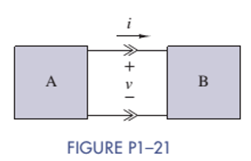
Two electrical devices are connected as shown in Figure P1-21. Using the reference marks shown in the figure, find the power transferred and state whether the power is transferred from A to B or B to A when
(a)
(b)
(c)
(d)
Want to see the full answer?
Check out a sample textbook solution
Chapter 1 Solutions
ANALYSIS+DESIGN OF LINEAR CIRCUITS(LL)
Additional Engineering Textbook Solutions
Introductory Circuit Analysis (13th Edition)
Electric Circuits (10th Edition)
Fundamentals of Applied Electromagnetics (7th Edition)
Electric Circuits. (11th Edition)
Basic Engineering Circuit Analysis
Electrical Engineering: Principles & Applications (7th Edition)


- Three 47.1 ohm resistors and three 17.1 H inductors are all in series with a 37 volt battery and a switch. The switch is placed in position A at time t = 0 and switched to position B at time t = 743 ms. Find the voltage across each of the resistors at time t = 1.17 seconds. Owo DO A R R in in ete SW éte لفظوarrow_forwardDetermine the value of the current measured by the ammeter in the Figure. Hint: Write and solve a single mesh equation. Determine the value of the current measured by the ammeter in Amperes.arrow_forwardA series circuit consists of three identical lamps are connected to a battery as shown in Figure below. The switch S, originally open, is closed. What then happens to the brightness of lamp B? A B C S Select one or more: a. It increases b. It does not change c. It decreases d. It drops to zero. + OOOOarrow_forward
- What is the voltage across the 50 Ohm and 5 Ohm resistors? Using the loop hole equation, what is the voltage across the R1? What is R1?arrow_forwardIn the figure &₁ = 3.82 V, &₂ = 1.32 V, R₁ = 5.14 Q, R₂ = 2.69 №, R₂ = 3.61 N, and both batteries are ideal. What is the electric current in (a) R₁, (I₁) (b) R₂, (1₂) and (c) R3, (13)? www R₁ -18₁ www R₂ R$ E₂f-arrow_forwardI did a physics lab and got some values. I want to check them theoretically to see how the results differ. From this diagram, answer the following questions: The laws to be verified included the conservation of current in a node, the addition of potentials for components in series, and the addition of currents for components in parallel. The data : R1: 1094 ohm R2 : 998 ohm R3: 1094 ohmR4: 25 ohm Source 1 : 5 V Source 2 : 1.5 Varrow_forward
- A circuit component carries a current of 2.4 amperes and has a voltage drop of 10 volts across it. What is the resistance R of the component? Round your answer to two significant figures. R = Number S2arrow_forwardThe figure below shows three resistors (R- 13.5 0, R -7.95 0, and Ry- 12.5 0) and two batteries connected in a circuit. 40.0 V R 22.0 V R3 (a) What is the current in each of the resistors? A I2 = A A (b) How much power is delivered to each of the resistors? P1- P2- P3-arrow_forward1. Solve for the voltage across resistor #5 (R5)? 2. Determine the voltage across resistor #3 (R3). 3. How much current is flowing through resistor #2 (R2)?arrow_forward
- What is current i2arrow_forwardA 25mv, 2mA dArsonval movement is to be used in voltmeter whose full scale reading is 100v. The resistance inserted by 100v meter into circuit is Select one: a. 1 x 10⁶ ohm b. None of all c. 1 x 10⁴ ohm d. 1 x 10⁵ ohm e. 1 x 10³ ohmarrow_forwardA current of 5 amperes enters a parallel combination of two unequal, unknown resistors (R1 and R2)supplied from a 45 volts DC source. If the two resistors are connected in series, the current drawnfrom the same source decreases to 937.5 mA. R1 has a lesser resistance than R2. Find R1 and R2.arrow_forward
 Introductory Circuit Analysis (13th Edition)Electrical EngineeringISBN:9780133923605Author:Robert L. BoylestadPublisher:PEARSON
 Delmar's Standard Textbook Of ElectricityElectrical EngineeringISBN:9781337900348Author:Stephen L. HermanPublisher:Cengage Learning
 Programmable Logic ControllersElectrical EngineeringISBN:9780073373843Author:Frank D. PetruzellaPublisher:McGraw-Hill Education
 Fundamentals of Electric CircuitsElectrical EngineeringISBN:9780078028229Author:Charles K Alexander, Matthew SadikuPublisher:McGraw-Hill Education
 Electric Circuits. (11th Edition)Electrical EngineeringISBN:9780134746968Author:James W. Nilsson, Susan RiedelPublisher:PEARSON
 Engineering ElectromagneticsElectrical EngineeringISBN:9780078028151Author:Hayt, William H. (william Hart), Jr, BUCK, John A.Publisher:Mcgraw-hill Education,