
ANALYSIS+DESIGN OF LINEAR CIRCUITS(LL)
8th Edition
ISBN: 9781119235385
Author: Thomas
Publisher: WILEY
expand_more
expand_more
format_list_bulleted
Videos
Textbook Question
Chapter 1, Problem 1.14P
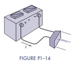
The 12-V automobile battery in Figure P1-14 has an output capacity of 100 Ah when connected to a head lamp that absorbs 200 W of power. The car engine is not running and therefore not charging the battery. Assume the battery volt-age remains constant.
- Find the current supplied by the battery and determine how long can the battery power the headlight.
- A 100-W device is connected through the utility port. How long can the battery power both the headlight and the device?
Expert Solution & Answer
Want to see the full answer?
Check out a sample textbook solution
Students have asked these similar questions
The figure shows an electric
circuit which contains a double switch labelled
by S. When the switch is in the position 11' the
ammeter reads I = 6 A, and when the switch is
in position 22' the reading is I1 =3A. What is
the reading on the ammeter when the switch is in
position 33'? The electromotive forces E of the
two batteries are equal, their internal resistances
and the internal resistance of the ammeter are
R,
R,
03
E
N
R,
03'
negligible.
E
In the figure R₁-3.41R, the ammeter resistance is zero, and the battery is ideal. What multiple of e/R gives the current in the ammeter?
EH
Number
Units
*E/R
Please answer it with further explanation. badly need it
What are your observations in this table below. How this reverse bias condition and forward bias condition affects current and voltage.
This data was simulated using multisim. You can notice the increasing value of battery voltage in 2nd column.
Chapter 1 Solutions
ANALYSIS+DESIGN OF LINEAR CIRCUITS(LL)
Ch. 1 - Given an electrical quantity described in terms of...Ch. 1 - Express the following quantities to the nearest...Ch. 1 - An ampere-hour (Ah) meter measures the time...Ch. 1 - Electric power companies measure energy...Ch. 1 - Fill in the blanks in the following statements. To...Ch. 1 - Which of the two entries is larger? 1000...Ch. 1 - A wire carries a constant current of 30A. How many...Ch. 1 - The net positive charge flowing through a device...Ch. 1 - Figure P1-9 shows a plot of the net positive...Ch. 1 - The net negative charge flowing through a device...
Ch. 1 - A cell phone charger outputs 9.6 V and is...Ch. 1 - For 0t5s, the current through a device is...Ch. 1 - The charge flowing through a device is...Ch. 1 - The 12-V automobile battery in Figure P1-14 has an...Ch. 1 - The current through a device is zero for t0 and is...Ch. 1 - A string of holiday lights is protected by a 12A...Ch. 1 - When illuminated the relationship for a photocell...Ch. 1 - A new 6-V alkaline lantern battery delivers...Ch. 1 - The maximum current allowed by a device's power...Ch. 1 - Traffic lights are being converted from...Ch. 1 - Two electrical devices are connected as shown in...Ch. 1 - Figure P1-22 shows an electric circuit with a...Ch. 1 - Figure P1-22 shows an electric circuit with a...Ch. 1 - In Figure P1-24 the voltage v2 is 10 V and v4 is 5...Ch. 1 - For t0, the voltage across and power absorbed by a...Ch. 1 - Repeat Problem 1-22 using MATLAB to perform the...Ch. 1 - Using the passive sign convention, the voltage...Ch. 1 - Power Ratio (PR) in dB A stereo amplifier takes...Ch. 1 - AC to DC Converter A manufacturer's data sheet for...Ch. 1 - Charge-Storage Device A capacitor is a...Ch. 1 - Compute Data Sheet A manufacturer's data sheet for...Ch. 1 - Light Source Comparison A Today people have three...
Additional Engineering Textbook Solutions
Find more solutions based on key concepts
Find Vo in the network in Fig. P5.4 using linearity and the assumption that Vo=1V.
Basic Engineering Circuit Analysis
The resistance and inductance of the circuit in Fig. 8.5 are 100 and 20 mH, respectively.
Find the value of C t...
Electric Circuits. (11th Edition)
The switch in the circuit shown has been closed for a long time and is opened at t = 0.
Calculate the initial v...
Electric Circuits (10th Edition)
Explain Faradays law and the function of Lenzs law.
Fundamentals of Applied Electromagnetics (7th Edition)
a. Using the superposition theorem, determine the voltage across the 4.7 resistor of Fig. 9.126. b. Find the p...
Introductory Circuit Analysis (13th Edition)
Suppose we have a capacitance C discharging through a resistance R. Define and give an expression for the time ...
Electrical Engineering: Principles & Applications (7th Edition)
Knowledge Booster


Learn more about
Need a deep-dive on the concept behind this application? Look no further. Learn more about this topic, electrical-engineering and related others by exploring similar questions and additional content below.Similar questions
- The circuit shown below is an example of a simple voltage regulator. Determine the current through R1 in mA. Assume the following values for the resistors: R1 = 11 kQ, R2 = 20 kQ. Express your answer using three decimal places. Assume the opamp is ideal and Q1's B is infinity. Q1 VCC Vref NPN U1 OUT 20V 1.2V R1 R2 wW WWDarrow_forwardWhat is the voltage of UR1 falling on the resistor R1 in the circuit given in the figure?arrow_forwardThe figure shows an electric circuit which contains a double switch labelled by S. When the switch is in the position 11' the ammeter reads I = 6 A, and when the switch is in position 22' the reading is I1 =3 A. What is the reading on the ammeter when the switch is in position 33'? The electromotive forces E of the two batteries are equal, their internal resistances and the internal resistance of the ammeter are R, 03 E N R, 03' negligible. Earrow_forward
- Consider the circuit in the given figure. ASsume R1 = 180 2 and R2 = 290 Q. R R2 40 V Calculate current / in the given figure when the switch is in position 2. The current when the switch is in position 2 is mA. wwarrow_forwardIn the figure below you see the sketches for the front and back of an electrical circuit board. The board is cut into a trapezoidal shape and is made of plastic. On the back of the board there is conductive paint shown here in green. On the front there are some resistors and capacitors, in addition to terminals for inserting the leads from a DC power supply. The legs of the resistors and capacitors go through the holes on the board and are soldered to the conducting paint on the back side. You also have a multi-meter which you can use as an ammeter or a voltmeter. 16 v 4700 16 10 8 O- 7 3. 6. 4 O+arrow_forward14. A 6-V lead-acid battery has an A-hr rating of 180 A-hr. The battery is to be load-tested. What should be the test current, and what are the maximum permissible amount and duration of the voltage drop?arrow_forward
- 39. You and your lab partner have built the circuit shown in Figure 1.56. The three resistors, R1, R2 and R3 all have resistances of 1 k2, while the two voltage sources have 5 V and 3 V (as shown). The circuit has two output terminals, A and B. Answer the following questions about the circuit. (NOTE: The orientation of the voltage sources is important.) (a) What is the voltage drop across R1 R2 R3 A 5 V 3 V B Figure 1.56: The circuit for problem 39. R3? (b) What is the current flowing through R1? (c) Sketch the Thévenin equivalent circuit as seen looking into the terminals A and B. What is the Thévenin voltage, Vth, of the circuit? (d) What is the power supplied by the two voltage sources? (e) In order to safely determine the Thévenin resistance of your circuit, you connect a fourth resistor, R4 = 1 k2, between A and B. Using your trusty yellow DVM, you measure a potential difference across R4 to be 0.4 V. Using %3Darrow_forwardThe hot resistance of an incandescent lamp is 10 ohms and the rated voltage is 50 V. Find the series resistance required to operate the lamp from an 80 V supplyarrow_forwardFor the circuit below, determine the resistor voltage. The source is 5 volts, the Zener potential is 5.2 volts and the resistor is 1k ohms.arrow_forward
- A 12-V DC automobile head lamp is to be used on a fishing boat with a 24-V power system. The head lamp is rated at 50 W. A resistor is to be connected in series with the lamp to permit it to operate on 24 V. What should be the resistance and power rating of the resistor?arrow_forwardDetermine the current flowing through the resistor R1 if the Zener voltage is 4V.arrow_forwardIn the figure below you see the sketches for the front and back of an electrical circuit board. The board is cut into a trapezoidal shape and is made of plastic. On the back of the board there is conductive paint shown here in green. On the front there are some resistors and capacitors, in addition to terminals for inserting the leads from a DC power supply. The legs of the resistors and capacitors go through the holes on the board and are soldered to the conducting paint on the back side. You also have a multi-meter which you can use as an ammeter or a voltmeter. 16 v 4700 16 10 8 O- 7 3. 6. 4 O+arrow_forward
arrow_back_ios
SEE MORE QUESTIONS
arrow_forward_ios
Recommended textbooks for you
 Delmar's Standard Textbook Of ElectricityElectrical EngineeringISBN:9781337900348Author:Stephen L. HermanPublisher:Cengage Learning
Delmar's Standard Textbook Of Electricity
Electrical Engineering
ISBN:9781337900348
Author:Stephen L. Herman
Publisher:Cengage Learning
Lesson 2 - Source Transformations, Part 2 (Engineering Circuits); Author: Math and Science;https://www.youtube.com/watch?v=7gno74RhVGQ;License: Standard Youtube License