
The time
Answer to Problem 5.79HP
The value of
Explanation of Solution
Calculation:
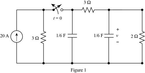
The given circuit is shown in Figure 1
For time
The required diagram is shown in Figure 2
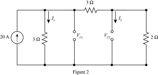
The value for the current through the resistance of
The value for the current through the resistance of
The expression for the initial voltage across the capacitor
Substitute
The expression for the initial voltage across the capacitor
Substitute
For time
The required diagram is shown in Figure 3
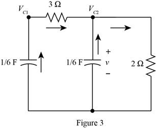
Apply KCL to the node
Substitute
Apply KCL to the node
Substitute
Substitute
The standard second order equation for the above equation is given by,
From above and from equation (2), the natural frequency of the circuit is calculated as,
The damping ratio of the circuit is calculated as,
Substitute
The general equation for the voltage across the capacitor is given by,
Substitute
Substitute
Substitute
Substitute
Apply KCL to the node
Substitute
Substitute
The differentiation of equation (3) with respect to
Substitute
Substitute
Substitute
Substitute
Substitute
Substitute
Substitute
Thus, the value of
Conclusion:
Therefore, the value of
Want to see more full solutions like this?
Chapter 5 Solutions
Principles and Applications of Electrical Engineering

- For t > 0, determine for what value of t v = 7.5 Vin the circuit of Figure P5.79 if the circuit is in steadystate at t = 0−.arrow_forwardAssume the circuit of Figure P5.72 initially storesno energy. Switch S1 is open and S2 is closed. SwitchS1 is closed at t = 0, and switch S2 is opened at t = 5 s.Determine an expression for the capacitor voltagefor t ≥ 0.arrow_forwardB Determine the voltage across the inductor just before and just after the switch is changed in Figure P5.38. Assume steady-state conditions exist for t < 0. Vs = 12 V Rs = 0.24 2 R = 33 k2 L = 100 mH t= 0 Rs + EIarrow_forward
- '8 For t> 0, determine for what value of t i = 6 A in the circuit of Figure P5.78 if the circuit is in steady state at t= 0-. ww 40 V wwarrow_forward6 Determine the voltage across the inductor just before and just after the switch is changed in Figure P5.26. Assume steady-state conditions exist for t < 0. Vs = 12 V R, = 0.7 2 R = 22 k2 L= 100 mH 1=0 R, R1arrow_forward7 In the circuit shown in Figure P5.67, assume that DC steady-state conditions exist for t < 0. Determine at t = 0+, just after the switch is opened, the current through and voltage across the inductor and the capacitor and the current through Rs2. Vsi = 15 V Rsi = 130 2 V2 = 9 V Rs = 290 2 R = 1.1 k2 R2 = 700 2 L = 17 mH C = 0.35 µF t= 0 Rs1 R1 Vs1arrow_forward
- Assume the circuit of Figure P5.70 initially storesno energy. The switch is closed at t − 0. Finda. Capacitor voltage as t approaches infinityb. Capacitor voltage after 20 μsc. Maximum capacitor voltagearrow_forwardFor the circuit of Figure P5.70, determine if it isunderdamped or overdamped. Find also the capacitorvalue that results in critical dampingarrow_forwardWrite the differential equation for t > 0 for thecircuit of Figure P5.27.arrow_forward
- Determine the initial and final conditions for thecircuit of Figure P5.49arrow_forwardDescribe the steady-state similarities and differences of DC and AC circuits with purelyresistive elementsarrow_forwardDerive the expressions of voltages across resistor and capacitor and the current through the circuit in charging and discharging phases of an RC circuit excited by DC voltage. Name some uses of transient currents. 2.arrow_forward
 Introductory Circuit Analysis (13th Edition)Electrical EngineeringISBN:9780133923605Author:Robert L. BoylestadPublisher:PEARSON
 Delmar's Standard Textbook Of ElectricityElectrical EngineeringISBN:9781337900348Author:Stephen L. HermanPublisher:Cengage Learning
 Programmable Logic ControllersElectrical EngineeringISBN:9780073373843Author:Frank D. PetruzellaPublisher:McGraw-Hill Education
 Fundamentals of Electric CircuitsElectrical EngineeringISBN:9780078028229Author:Charles K Alexander, Matthew SadikuPublisher:McGraw-Hill Education
 Electric Circuits. (11th Edition)Electrical EngineeringISBN:9780134746968Author:James W. Nilsson, Susan RiedelPublisher:PEARSON
 Engineering ElectromagneticsElectrical EngineeringISBN:9780078028151Author:Hayt, William H. (william Hart), Jr, BUCK, John A.Publisher:Mcgraw-hill Education,