
Concept explainers
Videos
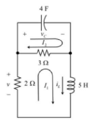
The inductor current IL, voltage 'v' across the 2Ω resister and voltage
Answer to Problem 5.72HP
Explanation of Solution
Given:
The given circuit is shown below.
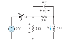
The switch is closed at t = 0 s and reopened at t = 5 s.
Calculation:
The capacitor does not allow the sudden change in voltage and the inductor does not allow the sudden change in current.
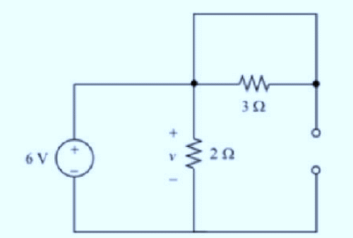
At t = 0, the capacitor behaves like short circuit and inductor behaves like open circuit.
The modified circuit diagram is:
From the circuit,
Relation between inductor current and voltage is:
Considering the following circuit, at
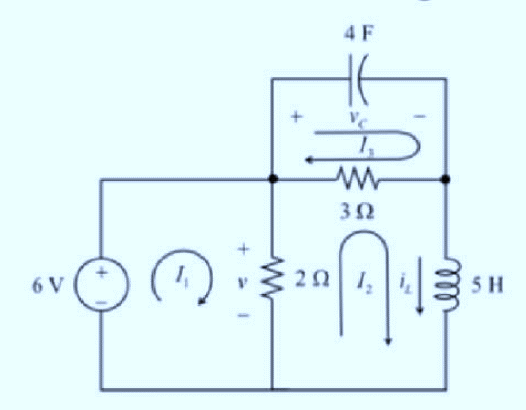
Applying Kirchhoff's voltage law in loop1,
Applying Kirchhoff's voltage law in top loop,
Differentiating the equation with respect to t,
Applying Kirchhoff's voltage law in bottom loop,
From equation 1, putting the value of
From equation 2, putting the value of
Differentiation of any constant value is zero.
Writing the equation in standard second order differential equation:
Dividing by 0.75,
Comparing the equation with standard second order differential equation:
The natural frequency is determined as:
The damping ratio is determined as follows:
The value of damping ratio is less than 1.
Hence, it is an underdamped second order circuit.
The following expression is used to solve the complete solution.
The roots
At t = 0, the inductor's natural response current is zero.
Differentiating the above equation and substituting t = 0,
Substituting,
Thus, expression for inductor current is:
The voltage across the inductor is:
The voltage across the resistor is:
The voltage across the capacitor is:
Considering that at t = 5 s, the switch moved to open position.
The initial value of the inductor current is:
The initial value of the capacitor voltage is:
Considering the following circuit to determine the initial values:
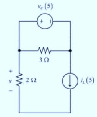
The inductor voltage:
Considering the following circuit for t > 5 s.
Applying Kirchhoff's voltage law in top loop,
Differentiating the equation with respect to t,
Applying Kirchhoff's voltage law in bottom loop,
Comparing with standard second order equation:
The natural frequency is determined as:
The damping ratio is determined as follows:
The value of damping ratio is less than 1.
Hence, it is an underdamped second order circuit.
The following expression is used to determine the complete solution:
The roots
Substituting
Hence, the expression of inductor current is:
The voltage of inductor is:
The voltage of 2O resistor:
The voltage across capacitor is:
Want to see more full solutions like this?
Chapter 5 Solutions
Principles and Applications of Electrical Engineering


- Consider the R-C circuit. We removed the battery. We begin the capacitor initially fully charged. At initial time t=0, the switch was closed. Ans the questions that followsarrow_forwardFor the figure, the circuit has reached the steady statewith the switch closed. Now the switch opens.a) Determine the time constant of the circuitde-energized.b) Determine the equation for the currentinductor.c) Find the inductor current at time t = 17.8µS.arrow_forwardIn the circuit shown in Figure 1, find the values of R and C such that the steady-state voltage across the capacitance and the time constant of the response for t> 0 are -10V and 20 seconds respectively. Place all the details of your design.arrow_forward
- Determine the energy in the inductor for the circuit shown under steady-state conditions. Enter your value of energy stored in units of J Show all workarrow_forward8 For t > 0, the circuit shown in Figure P5.22 is at steady state. The switch is changed as shown at t = 0. Vsi = 35 V C = 11 µF Vsz = 130 V R = 17 k2 R = 7 k2 R = 23 k2 Determine the time constant of the circuit for t> 0.arrow_forwardGiven circuit below, use superposition to find voltage across the capacitor, vclt). Frequency is 100 Hz. 6kn 4kn reee zkn O SmA <45 Vc (t) DC a) Given circuit below and switch ciosed for long time, what is the value of Vc? 5mA 3 luk bị At0, switch is opened. Write a mathematical expression for Velt) after opening of the switch. Evaluate this voltage at te10 ms. Attach File Browse Local Fies rowie Conent Cotection 74°Farrow_forward
- The time taken by the series RL circuit having an inductance of 0.6 H and resistance of 30 Ohms to reach a steady-state value.arrow_forwardHome Work In the figure below, the switch has been open for a significant period of time. The switch is closed at t3D0. Find the current through the resistor at t=0+, and at t=1.25s. Find the energy in the inductor at t=1.25s. 50V 8H 202arrow_forwardRC Circuits in Applications of First-OrderDifferential Equations A 1-F capacitor is connected in series with a 6-ohm resistor. If the connection is energized from a 9-V DC source, determine the voltage (in volts) across the capacitor for a long time. The initial current is 100 mC.arrow_forward
- QI/ For the network shown in figure (Qi), the switch has been in position "a" for a long time. At t-0, the switch moves and stays at position "b". Determine an expression for the inductor current in(t) when 20 using the general solution formula. 5a ilt) tso b. lomH 72Varrow_forwardIs the circuit currently in steady-state or transient condition? Justify your answer. Based on the plots, is the circuit in steady-state or in transient condition after the closure of the switch BUT before the plots become horizontal? Justify your answer. Is the inductor behaving like a short circuit after the plots become horizontal? Why?arrow_forwardThe figure on the right shows an RL circuit connected to a battery. Assume that the inductor is initially uncharged. What is the direction of the self-induced current in the inductor shortly after the circuit is completed as compared to the current created by the battery? Why?arrow_forward
 Introductory Circuit Analysis (13th Edition)Electrical EngineeringISBN:9780133923605Author:Robert L. BoylestadPublisher:PEARSON
 Delmar's Standard Textbook Of ElectricityElectrical EngineeringISBN:9781337900348Author:Stephen L. HermanPublisher:Cengage Learning
 Programmable Logic ControllersElectrical EngineeringISBN:9780073373843Author:Frank D. PetruzellaPublisher:McGraw-Hill Education
 Fundamentals of Electric CircuitsElectrical EngineeringISBN:9780078028229Author:Charles K Alexander, Matthew SadikuPublisher:McGraw-Hill Education
 Electric Circuits. (11th Edition)Electrical EngineeringISBN:9780134746968Author:James W. Nilsson, Susan RiedelPublisher:PEARSON
 Engineering ElectromagneticsElectrical EngineeringISBN:9780078028151Author:Hayt, William H. (william Hart), Jr, BUCK, John A.Publisher:Mcgraw-hill Education,