
Concept explainers
Videos
The current
Answer to Problem 5.65HP
The value of current
Explanation of Solution
Calculation:
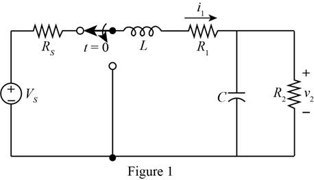
The given diagram is shown in Figure 1
The conversion from
The conversion from
The conversion from
The conversion from
The conversion from
The conversion from
The conversion from
For time
The required diagram is shown in Figure 2

From above, the expression for the current
The inductor opposes the sudden change in the current, thus the current
Substitute
The expression for the voltage across the capacitor for time
Substitute
The expression for the voltage across the capacitor for time
Substitute
The capacitor opposes the sudden change in the voltage and acts as a short circuit. Change the switch position, mark the values and redraw the circuit for
The required diagram is shown in Figure 3
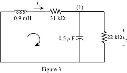
Apply KCL to the top node of the above circuit.
Apply KVL in the left loop of the above circuit.
Substitute
Substitute
The roots of the above differential equation are given by,
The expression for the voltage
Substitute
Substitute
Substitute
The differentiation of
Substitute
Substitute
Substitute
Substitute
From above and from equation (3), the evaluated value of the constant
Substitute
Substitute
Substitute
Substitute
Substitute
Conclusion:
Therefore, the value of current
Want to see more full solutions like this?
Chapter 5 Solutions
Principles and Applications of Electrical Engineering


- *P5.53. Solve for the node voltages shown in Figure P5.53. 10 Ω I₁ V₁ +j20 Ω 10/0° + V₂ 1₂ - Figure P5.53 15 Ω 13 es a - - j5 Ωarrow_forwardA resistive circuit was connected to a variable resistor, and the power delivered to the resistor was measured as shown in Figure P 5.6-9. Determine the Thévenin equivalent circuit. Figure P 5.6-9 Power (W) 10 20 30 40 R (ohms)arrow_forward1)The value of the capacitance reactive power in VAR is? /2) The value of the capacitor in micro farad is?arrow_forward
- C5 What is the correct explanation for the voltage seen at Va in Figure C5? Va 1 Sost We will assume that the Vout Out Vb, capacitor is charged to a value determined by the feedback and the supply voltage +BVsat. Figure C5 A. The waveform on the capacitor looks like a discharge, and then a charging waveform to an equal but opposite magnitude voltage, B. The capacitor simply reverses its charge, with a charging waveform, C. The capacitor simply reverses its charge, with a discharging waveform, D. None of the above.arrow_forward5.1 Find V, in the circuit shown in Figure P5.1. FIGURE P5.1 0.5 V Vs R₁ www 1 ΚΩ ti + U₁ R₂ 6 ΚΩ OUTarrow_forwardP5.43. Find the complex impedance of the network shown in Figure P5.43 for w=500. Repeat for w= 1000 and w= 2000.arrow_forward
- Using the series circuit in Figure 3 consisting of a voltage source V, the resistor R and the fully uncharged capacitor C, how to find the value of the capacitance C considering as known data the time constant of the circuit T and the value of the resistor R? V ww Rarrow_forward3-10 A0.25-F capacitor has a current waveform i(t) as shown in Figure P3–10. Determine and plot the voltage waveform v(t) as a function of time. The capacitor is initially a and plot the voltage waveform v(t) as a function of time. The capacitor is imu uncharged. FIGURE P3-10 ilt) 4 A 6. -4 Aarrow_forwardLet's say you measure t1/2 to be 0.037 seconds and the resistance in the circuit is 68 Ohms. Then what is the capacitance in micro Farads? Answer in micro Farads.arrow_forward
- (VD₂ = Determine the voltage across each capacitor in the circuit figure below. 0.68 V, VD₂ 0.56 V) = 240 V rms 50 Hz 1:1 ooooo elele C₁ H 1μF D₁ HE D₂ .C₂ 1 μFarrow_forwardA series R–L–C circuit comprises a 5µF capacitor, a 4ohm resistor and a variable inductance L. The supply voltage is 10∠0◦ V at a frequency of 159.1 Hz. The inductance is adjusted until the p.d. across the 4 ohm resistanceis a maximum. Determine for this condition (a) the value of inductance, (b) the p.d. across each component and (c) the Q-factor of the circuit.arrow_forwardA resistor of 20 Ohms and a capacitance of unknown value when connected in in parallel across a 100V, 50Hz supply, take a current of 6A. The combination is now connected across a 100v supply of unknown frequency and the current falls to 5.5A. What is the frequency?arrow_forward
 Introductory Circuit Analysis (13th Edition)Electrical EngineeringISBN:9780133923605Author:Robert L. BoylestadPublisher:PEARSON
 Delmar's Standard Textbook Of ElectricityElectrical EngineeringISBN:9781337900348Author:Stephen L. HermanPublisher:Cengage Learning
 Programmable Logic ControllersElectrical EngineeringISBN:9780073373843Author:Frank D. PetruzellaPublisher:McGraw-Hill Education
 Fundamentals of Electric CircuitsElectrical EngineeringISBN:9780078028229Author:Charles K Alexander, Matthew SadikuPublisher:McGraw-Hill Education
 Electric Circuits. (11th Edition)Electrical EngineeringISBN:9780134746968Author:James W. Nilsson, Susan RiedelPublisher:PEARSON
 Engineering ElectromagneticsElectrical EngineeringISBN:9780078028151Author:Hayt, William H. (william Hart), Jr, BUCK, John A.Publisher:Mcgraw-hill Education,