
Concept explainers
Videos
Two thin convex lenses and an object are arranged as shown below. Two rays from the tip of the object are drawn in order to determine the location of the image produced by lens 1. Lens 2 is placed so that one of its focal points coincides with the location of the image produced by lens 1.
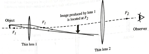
e. The diagram in this problem illustrates a compound microscope. Lens 1, called the objective,is placed near the object of interest. Lens 2, known as the eyepiece, is placed so that one of focal points coincides with the image produced by the objective.
In order to improve the angular magnification of the microscope shown above, would you replace the eyepiece (lens 2) with another lens that has a smaller focal length or a larger focal length? Explain your reasoning.
Want to see the full answer?
Check out a sample textbook solution
Chapter 24 Solutions
Tutorials in Introductory Physics
Additional Science Textbook Solutions
Conceptual Physical Science (6th Edition)
Conceptual Integrated Science
Physics for Scientists and Engineers with Modern Physics
Applied Physics (11th Edition)
College Physics: A Strategic Approach (4th Edition)


- A converging (concave) mirror with a focal length of 7 cm is held 4 cm from your face. a. Determine the image location. Insert your solution here: b. What is the magnification of the image? Use the formula belowarrow_forwardAn object stands on the common central axis of two thin, symmetric lenses. The object is placed 15.0 cm in front of the first lens (converging lens) whose focal length is 10.0 cm. The second lens is a diverging lens whose focal length is also 12.0 cm. The distance between the lenses is 40.0 cm. a.) Determine the characteristics of the final image by using thin-lens and magnification equations. Give your reasoning. b.) Find the location of the final image by using ray diagrams (sketch the rays clearly). Object f₁ 15 cm 1st Lens f₁ 40 cm 420 2nd Lensarrow_forwardTwo converging lenses with focal lengths of 40 cm and 21 cm are 12 cm apart. A 4.0-cm-tall object is 15 cm in front of the 40-cm-focal-length lens. Part A Calculate the position of the final image (relative to the 21-cm-focal-length lens). Express your answer to two significant figures and include the appropriate units. Enter a positive value if the image is on the other side from the lens and a negative value if the image is on the same side. Submitarrow_forward
- You hold a spherical salad bowl 50 cm in front of your face with the bottom of the bowl facing you. The salad bowl is made of polished metal with a 48 cm radius of curvature. Part A Where is the image of your 5.0-cm-tall nose located? Follow the sign rules. Enter the magnitude of the distance from the salad bowl. Express your answer with the appropriate units. s' Submit Part B Value y' = Request Answer What is the image's size? Express your answer with the appropriate units. μА Units Value Units ? ?arrow_forwardA lens has 2 focal points or foci as shown in the drawings below... A. A convex-convex lens is a converging lens. P rays that enter the lens from the left side will converge at and pass through the focal point on the right or far side. The focal point on the left or near side is not used. Sketch three P rays passing through the converging lens provided. Note: Instead of refracting the ray at each interface, assume the ray refracts only once, at the dashed central bisector of the lens B. A concave-concave lens is a diverging lens. P rays entering from the left will diverge away from the focal point on the left. The right side focal point is not used. Sketch 3 P rays passing through the diverging lens provided.arrow_forwardA nature photographer taking a close-up shot of an insect replaces the standard lens on his camera with a lens that has a shorter focal length and is positioned farther from the CCD detector. Part A Explain why he does this. Drag the terms on the left to the appropriate blanks on the right to complete the sentences. Reset Help 1 The object distance, image distance, and focal length are related by f smaller 1 1 Inspecting this expression, we see that for a fixed focal length, as the object s' f distance gets smaller the image distance must get in order to +! = } f maintain the equality. s' larger Due to the construction of the camera, there is a limit to how big the image distance can be and still get a sharp image on the detector. In order to allow smaller object distances (which is the case for a close-up shot), the photographer can use a focal length lens.arrow_forward
- In the two-lens system shown, f1 = -12.0 cm, f2 = 4.0 cm, and the lenses are a distance d = 5.0 cm apart. An object of height h = 1.0 cm is placed a distance l = 4.0 cm to the left of the diverging lens. a. Where is the final image formed by this system of lenses? Give your answer as a specific distance to the left or right of the converging lens. b. What are the height and orientation of the final image?arrow_forwardPart A The diagram below shows the situation described in the problem. The focal length of the lens is labeled f; the scale on the optical axis is in centimeters.Draw the three special rays Ray1, Ray2, and Ray3 as described in the Tactics Box above, and label each ray accordingly. Draw the rays from the tip of the object to the lens. Do not draw the refracted rays. Draw the vectors starting from the tip of the object. The location and orientation of the vectors will be graded. The length of the vectors will not be graded. +, Vectors: Ray3 Ray through center of lens Ray2 Ray toward far focal point Rayl Ray parallel to axis Unlabeled vector Object 1arrow_forwardYou are imaging a pencil through a thin, converging lens as shown in the image below. If p (the distance from the object to the center of the thin lens) is 8.15m and the focal length of the thin lens is 0.42m, how far away (in meters) from the center of the thin lens is the real image located (the real image will be on the right-side of the lens in this particular example illustrated below)? Ray 1 Ray 1 focal point Ray 2 Sis Secondary Ray 3 Ray 3 Object Converging lens focal point Principal Real image Note: Do not explicitly include units in your answer (it is understood the unit is meter). Enter only a number. If you do enter a unit, your answer will be counted wrong.arrow_forward
- An insect 1.5 mm tall is placed 1.0 mm beyond the focal point of the objective lens of a compound microscope. The objective lens has a focal length of 12 mm, the eyepiece has a focal length of 26 mm. For related problem-solving tips and strategies, you may want to view a Video Tutor Solution of A simple magnifier. Show Transcribed Text Part A Where is the image formed by the objective lens? Give your answer as the distance from the image to the lens. Express your answer with the appropriate units. s₁ = Submit Part B m₁ = μA Submit Value Request Answer What is the magnification, including the correct sign, of the objective image? 15. ΑΣΦ Request Answer Units Show Transcribed Text 2 ? ?arrow_forwardAn object O is placed at the location shown in front of a concave spherical mirror. Use ray tracing to determine the location and size of the reflected image. As you work, keep in mind the following properties of principal rays: Part A Trace the path of a ray emitted from the tip of the object through the focal point of the mirror and then the reflected ray that results. Start by extending the existing ray emitted from the tip of the object. Then create the reflected ray. 1. A ray parallel to the axis, after reflection, passes through the focal point Fof a concave mirror or appears to come from the (virtual) focal point of a convex mirror. 2. A ray through (or proceeding toward) the focal point Fis reflected parallel to the axis. 3. A ray along the radius through or away from the center of curvature C intersects the surface normally and is reflected back along its original path 4. A ray to the vertex Vis reflected, forming equal angles with the optic axis. Draw the vector for the…arrow_forward(c) A set of parallel rays are incident on the mirror shown in the diagram below. C is the centre of curvature of the mirror. Sketch this diagram in your answer sheet. i. Identify the type of mirror. ii. Indicate the position of the focus, F, on your sketch. iii. On your diagram indicate the paths followed by each of the rays after reflection from the mirror. iv. Is the focus real or virtual? Why?arrow_forward
 College PhysicsPhysicsISBN:9781305952300Author:Raymond A. Serway, Chris VuillePublisher:Cengage Learning
 University Physics (14th Edition)PhysicsISBN:9780133969290Author:Hugh D. Young, Roger A. FreedmanPublisher:PEARSON
 Introduction To Quantum MechanicsPhysicsISBN:9781107189638Author:Griffiths, David J., Schroeter, Darrell F.Publisher:Cambridge University Press
 Physics for Scientists and EngineersPhysicsISBN:9781337553278Author:Raymond A. Serway, John W. JewettPublisher:Cengage Learning
 Lecture- Tutorials for Introductory AstronomyPhysicsISBN:9780321820464Author:Edward E. Prather, Tim P. Slater, Jeff P. Adams, Gina BrissendenPublisher:Addison-Wesley
 College Physics: A Strategic Approach (4th Editio...PhysicsISBN:9780134609034Author:Randall D. Knight (Professor Emeritus), Brian Jones, Stuart FieldPublisher:PEARSON