
Concept explainers
Videos
Two thin convex lenses and an object are arranged as shown below. Two rays from the tip of the object are drawn in order to determine the location of the image produced by lens 1. Lens 2 is placed so that one of its focal points coincides with the location of the image produced by lens 1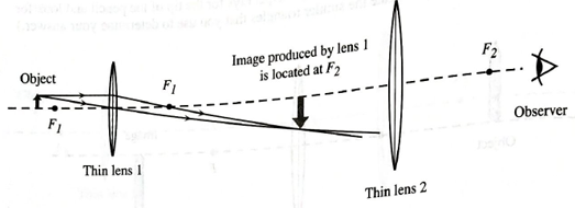
- Treating the image produced by lens 1 as an object for lens 2, draw two rays from the tip of this image that pass through lens 2. (Note that one of the principal rays cannot be drawn in this case.)
Using either geometry or trigonometry, show that these two principal rays are parallel on the right side of lens 2. (Hint: Look for congruent fight triangles in your ray diagram.)
Want to see the full answer?
Check out a sample textbook solution
Chapter 24 Solutions
Tutorials in Introductory Physics
Additional Science Textbook Solutions
Life in the Universe (4th Edition)
Physics for Scientists and Engineers: A Strategic Approach with Modern Physics (4th Edition)
College Physics: A Strategic Approach (4th Edition)
University Physics Volume 1
Conceptual Physical Science (6th Edition)
Applied Physics (11th Edition)


- An object is placed to the left of two converging lenses, as shown in (Figure 1). Lens 1 has a focal length f and lens 2 has a focal length 2f. The lenses are separated by a distance of 6 f. An object of height h is then placed a distance of 2f to the left of lens 1. Calculate the following quantities in terms of f and h (specify the Figure "↑ 1 of 1 Part A Start solving the problem by constructing a sketch of the lens system and indicating the focal points of each lens. Write down the thin-lens equation. Express your answer in terms of the focal length f, the object so, and image si distances, if needed. ► View Available Hint(s) VE ΑΣΦ 16f 3 Submit Previous Answers ? X Incorrect; Try Again; 5 attempts remainingarrow_forwardMY QUESTION: Refer back to problem # 4, part c, on the two-lens system. Draw a ray diagram using 3 rays from object # 2 – the object for lens 2 – to identify the final image produced by the two-lens system. Make your diagram neat and clearly labeled. [Given the size of the two lens system, I recommend making the drawing on a separate page with the page turned sideways in landscape orientation.]arrow_forwardYou are imaging a pencil through a thin, converging lens as shown in the image below. If p (the distance from the object to the center of the thin lens) is 8.15m and the focal length of the thin lens is 0.42m, how far away (in meters) from the center of the thin lens is the real image located (the real image will be on the right-side of the lens in this particular example illustrated below)?arrow_forward
- An object is placed near a lens as shown below. The dots represent the focal points of the lens. -0.10 +0.10 At what distance from the lens could the object be placed to produce a virtual image that is smaller than the object (where M < 1)? There is no place where this is possible at -0.10 m only at either -0.25 m or +0.25 m at either -0.05 m or +0.05 marrow_forwardCase 5: Object located in focus (d0= F'). The figure below shows an arrow-shaped object, placed in front of a convex lens at a distance d0 equal to a focal length (d0=F'). Draw the following rays in the figure: ray parallel to the optical axis, central ray. Don't forget to put the direction on each ray, both the incident rays and the transmitted rays. Label each ray with its name. Image characteristics for Case 5: Object located in focus (d0= F'). Choose the ones that apply: a) Virtual b) Real c) Inverted d) Increased e) No image is formed f) Equal size g) Reduced h) Erect Case 6: Object located between the focus and the vertex of a convex lens (d0< F'). The figure below shows an arrow-shaped object, placed in front of a convex lens at a distance d0 less than a focal length (d0<F'). Draw the following rays in the figure: ray parallel to the optical axis, focal ray, central ray. Draw the image of the arrow, indicate in the same figure from where to where di is (image-lens…arrow_forwardFind the image distance and image height of the image formed on the following cases. Then, describe whether the image formed is on the same or opposite side of the object, upright or inverted image, and smaller or bigger than the object. 4) A 19-cm high object is placed 71 cm from a converging lens. The focal length is 35 cm. 5) A 26.50-cm high object is placed 40 cm from a diverging lens. The focal length is 20 cm.arrow_forward
- A lens with a focal length of 15 cm is placed 40 cm in front of a lens with a focal length of 5.0 cm. Part A: How far from the second lens is the final image of an object infinitely far from the first lens?arrow_forwardLens L, in the figure below has a focal length of 14.0 cm and is located a fixed distance in front of the film plane of a camera. Lens L, has a focal length of 13.5 cm, and its distance d from the film plane can be varied from 5.00 cm to 10.0 cm. Determine the range of distances for which objects can be focused on the film. (Enter answers from smallest to largest.) Objects can be focused on the film from m to m. Film L2 -12.0 cmarrow_forwardA thin, diverging lens having a focal length of magnitude 45.0 cm has the same principal axis as a concave mirror with a radius of 60.0 cm. The center of the mirror is 20.0 cm from the lens, with the lens in front of the mirror. An object is placed 23.0 cm in front of the lens. 1)Where is the final image due to the lens–mirror combination? Enter the image distance with respect to the mirror. Follow the sign convention. (Express your answer to three significant figures.) 4)Suppose now that the concave mirror is replaced by a convex mirror of the same radius. Where is the final image due to the lens–mirror combination? Enter the image distance with respect to the mirror. Follow the sign convention. (Express your answer to three significant figures.)arrow_forward
- An object is 12.0 cm from a converging lens (focal length = 15.0 cm). Determine the image magnification. Enter the numerical part of your answer to two significant figures. Hint: Remember that the sign of the magnification is significant.arrow_forwardFigure 1 shows a curved surface separating a material with index of refraction n1 from a material with index n2. The surface forms an image I and object O? The center of curvature is point c For the ray that passes through the surface along a radial line, its angles of incidence and refraction are both zero, so its direction does not change at the surface. For the ray AB the direction changes according to Snell's law. Question Show that for small angle θ1 and θ2, the Snell's law can be written as n1 tan θ1 = n2 tan θ2arrow_forwardA small silver Christmas ball with a diameter of 6.25 cm was hanging on a Christmas tree. The Christmas ball was 0.40 m away from you, and you saw your reflection on its surface. Assuming that your height is 1.5 m, where and how tall is your image on the Christmas ball? Is it erect or inverted? Is it real or virtual? Draw a principal-ray diagram showing the formation of the image.arrow_forward
 College PhysicsPhysicsISBN:9781305952300Author:Raymond A. Serway, Chris VuillePublisher:Cengage Learning
 University Physics (14th Edition)PhysicsISBN:9780133969290Author:Hugh D. Young, Roger A. FreedmanPublisher:PEARSON
 Introduction To Quantum MechanicsPhysicsISBN:9781107189638Author:Griffiths, David J., Schroeter, Darrell F.Publisher:Cambridge University Press
 Physics for Scientists and EngineersPhysicsISBN:9781337553278Author:Raymond A. Serway, John W. JewettPublisher:Cengage Learning
 Lecture- Tutorials for Introductory AstronomyPhysicsISBN:9780321820464Author:Edward E. Prather, Tim P. Slater, Jeff P. Adams, Gina BrissendenPublisher:Addison-Wesley
 College Physics: A Strategic Approach (4th Editio...PhysicsISBN:9780134609034Author:Randall D. Knight (Professor Emeritus), Brian Jones, Stuart FieldPublisher:PEARSON