
Tutorials in Introductory Physics
1st Edition
ISBN: 9780130970695
Author: Peter S. Shaffer, Lillian C. McDermott
Publisher: Addison Wesley
expand_more
expand_more
format_list_bulleted
Videos
Textbook Question
Chapter 11.2, Problem 3aT
Red light from a distant point source is incident on a mask with two identical, narrow vertical slits. The photograph at right illustrates the pattern that appears at the center of a distant screen.
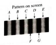
How does this pattern differ from what you would have predict if you had used the idea light travels in straight lines through slits?
Expert Solution & Answer
Want to see the full answer?
Check out a sample textbook solution
Students have asked these similar questions
For the next two questions, as seen in the image below, two materials A (na = 1.25) and
B ( 1.75) are stacked (ray angles for illustration only).
A
B
1. Monochromatic light hits A at an angle theta, -30° from the normal. What is the angle of
refraction of light that gets to come out from B?
A. None (total internal reflection occurs at B)
B. 60°
C. 30°
D. 15°
2. Suppose we want to induce the total internal reflection of light in this system by changing
either material A, B or adding another material below material B. Which of the following
changes would induce total internal reflection?
A. Adding a layer of material A below material B.
B. Replacing material A with material B.
C. Removing material B.
D. None of the above.
Two converging lenses, with focal lengths f1 and f2 are positioned a distance f1 + f2 apart, as shown in the figure below. Arrangements like this are called beam expanders and are often used to increase the diameters of light beams from lasers.
a. If W1 is the incident beam width, show that the width of the emerging beam is W2 = f2/f1 * W1b. Show how a combination of one diverging and one converging lens can also be arranged as a beam expander. Incident rays parallel to the axis should exit parallel to the axis
c. Calculate the ratio of the intensity of the beam emerging from the beam expander to the intensity of the laser beam.
that a ray incident on a 30° prism is deflected by 22.6° if the prism’s index of refraction is 1.59. Suppose that this is the index of refraction of deep violetlight, and that deep red light has an index of refraction of 1.54.a. What is the deflection angle for deep red light?b. If a beam of white light is dispersed by this prism, how wide is the rainbow spectrum on a screen 2.0 m away?
Chapter 11 Solutions
Tutorials in Introductory Physics
Ch. 11.1 - Prob. 1TCh. 11.1 - Prob. 2aTCh. 11.1 - Prob. 2bTCh. 11.1 - Prob. 2cTCh. 11.1 - The representation that we have been using...Ch. 11.1 - Prob. 2eTCh. 11.1 - Prob. 2gTCh. 11.1 - Each of the photographs at right shows a part of a...Ch. 11.1 - Obtain a piece of paper and a transparency with...Ch. 11.2 - Obtain a pan of water and form a barrier in it...
Ch. 11.2 - Prob. 2aTCh. 11.2 - Obtain an enlargement of the diagram at right that...Ch. 11.2 - Suppose that the width of one of the slits were...Ch. 11.2 - Red light from a distant point source is incident...Ch. 11.2 - Compare the situation in part II (in which a...Ch. 11.2 - For each of the lettered points, determine D (in...Ch. 11.2 - Suppose that one of the slits were covered. At...Ch. 11.2 - The pattern produced by red light passing through...Ch. 11.2 - Consider point B, the first maximum to the left of...Ch. 11.3 - Red light from a distant point source is incident...Ch. 11.3 - In a previous homework, you found an expression...Ch. 11.3 - Suppose that the screen were semicircular, as...Ch. 11.3 - Consider a point M on the distant screen where...Ch. 11.3 - Consider a point N on the screen where there is a...Ch. 11.3 - Obtain a set of transparencies of sinusoidal...Ch. 11.3 - Suppose that coherent red light were incident on a...Ch. 11.3 - Generalize your results from the 2-slit, 3-slit,...Ch. 11.3 - Coherent red light is incident on a mask with two...Ch. 11.3 - Prob. 3dTCh. 11.4 - Red light from a distant point source is incident...Ch. 11.4 - Suppose that point X marks the location of the...Ch. 11.4 - Suppose that only slit 1 is uncovered, and all...Ch. 11.4 - Show how you could group all ten slits into five...Ch. 11.4 - Suppose that the number of slits is doubled and...Ch. 11.4 - If we continued to add slits in this way (i.e.,...Ch. 11.4 - How is this pattern different from what you would...Ch. 11.4 - Consider the following dialogue: Student 1: "l...Ch. 11.4 - The photograph at right shows the diffraction...Ch. 11.4 - The photograph at right shows the diffraction...Ch. 11.4 - Describe what you would see on the screen if the...Ch. 11.4 - If a diffraction pattern has several minima (like...Ch. 11.4 - In part A, you drew a diagram that showed how find...Ch. 11.4 - Use the model that we have developed to write an...Ch. 11.5 - The minima that occur in the case of a single slit...Ch. 11.5 - Consider the following dispute between two physics...Ch. 11.5 - A second slit, identical in size to the first, is...Ch. 11.5 - Both slits are now uncovered. For what angles will...Ch. 11.5 - Suppose that the width of both slit, a, were...Ch. 11.5 - Suppose instead that the distance between the...Ch. 11.5 - The four graphs from part C that show relative...Ch. 11.5 - Consider the relative intensity graph shown at...Ch. 11.5 - Consider the following comment made by a student:...Ch. 11.5 - You may have already noticed that the maxima are...Ch. 11.6 - Prob. 1TCh. 11.6 - Prob. 2aTCh. 11.6 - When comparing two materials of different indices...Ch. 11.6 - Consider light incident on a thin soap film, as...Ch. 11.6 - Light of frequency f=7.51014Hz is incident on the...Ch. 11.6 - Suppose that an observer were located on the left...Ch. 11.6 - Observer A is looking at the part of the film that...Ch. 11.6 - Observer B is looking at the part of the film that...Ch. 11.6 - Observer C is looking at the thinnest part of the...Ch. 11.6 - Describe the appearance of the film as a whole.Ch. 11.6 - What are the three smallest film thickness for...Ch. 11.6 - The thickness of the film is 1650 nm at the bottom...Ch. 11.7 - Look at the room lights through one of the...Ch. 11.7 - Hold a second polarizing filter in front of the...Ch. 11.7 - Do the room lights produce polarized light?...Ch. 11.7 - Suppose that you had two marked polarizers (i.e.,...Ch. 11.7 - Suppose that you had a polarizer with its...Ch. 11.7 - Prob. 2dTCh. 11.7 - An observer is looking at a light source through...Ch. 11.7 - Consider a beam of unpolarized light that is...
Additional Science Textbook Solutions
Find more solutions based on key concepts
You work for a garden equipment company, and youre designing a new garden cart. Specifications to be listed inc...
Essential University Physics: Volume 1 (3rd Edition)
In what sense does physics underlie chemistry?
Conceptual Integrated Science
Why do SETI researchers assume that beacon signals would be designed for easy decoding, and how might we recogn...
Life in the Universe (4th Edition)
How can you see a virtual image, when its not really there?
Essential University Physics: Volume 2 (3rd Edition)
Choose the best answer to each of the following. Explain your reasoning. Which method could detect a planet in ...
Cosmic Perspective Fundamentals
Show that identical objects placed equal distances on either side of the focal point of a concave mirror or con...
Essential University Physics (3rd Edition)
Knowledge Booster


Learn more about
Need a deep-dive on the concept behind this application? Look no further. Learn more about this topic, physics and related others by exploring similar questions and additional content below.Similar questions
- a. Given the pattern of light on the far side of the prism, is the index of refraction inside the prism higher or lower than the index of refraction outside the prism? b. List at least one thing that is wrong with this diagram given what we expect the dependence of n on the wavelength of light to be (and assuming the prism is made of a uniform material). c. List at least one thing that is right with this diagram given what we expect the dependence of n on the wavelength of light to be (and assuming the prism is made of a uniform material).arrow_forwardA thin film of oil (no = 1.50) with varying thickness floats on water (nw = 1.33). When it is illuminated from above by white light, the reflected colors are as shown in the figure below. In air, the wavelength of yellow light is 580 nm. Why are there no reflected colors at point A? What is the oil’s thickness “t” at point B?arrow_forwardFor the picture below, determine the displacement of the light ray when the incident angle is 25°. The glass slab (? = 1.4) is 0.050 m thickarrow_forward
- Glass, despite being transparent, still reflects a little bit of light. When making lenses and such, you'd rather not waste any light with stray reflections. Fortunately, you can use destructive interference to suppress those reflections. The picture below shows a piece of glass with a coating of magnesium fluoride (MgF2). The arrows represent incoming light. Some of the light will reflect off the air-MgF2 interface. Some of the light will reflect off the MgF2-glass interface. If you can get these two portions of light to interfere destructively, there won't be any visible reflections. Use what you know about path length differences and interference to figure out how thick the coating of MgF2 needs to be for an anti-reflective coating for light of wavelength 640 nm. Use the thinnest coating possible. MgF2 has an index of refraction of 1.38 and the glass has an index of 1.58.Note: the wavelength given is the wavelength of the light in air.arrow_forwardA ray of light is incident on the left vertical face of a glass cube of refractive index n2, as shown in figure below. The plane of incidence is the plane of the page, and the cube is surrounded by liquid of refractive index n1. The largest angle of incidence 01 for which total internal reflection occurs at the top surface is (Hint; you may use sin ( – e) = cos(0))arrow_forwardTransmission through thin layers. In the figure, light is incident perpendicularly on a thin layer of material 2 that lies between (thicker) materials 1 and 3. (The rays are tilted only for clarity.) Part of the light ends up in material 3 as ray r3 (the light does not reflect inside material 2) and ra (the light reflects twice inside material 2). The waves of r3 and r4 interfere, and here we consider the type of interference to be either maximum (max) or minimum (min). The table below provides the indexes of refraction n, n2, and n3, the type of interference, and the thinlayer thickness L in nanometers. Give the wavelength that is in the visible range. n2 ng 14 n1 n2 n3 Туре L 1.35 1.84 1.45 min 335 Number Unitsarrow_forward
- Transmission through thin layers. In the figure, light is incident perpendicularly on a thin layer of material 2 that lies between (thicker) materials 1 and 3. (The rays are tilted only for clarity.) Part of the light ends up in material 3 as ray r3 (the light does not reflect inside material 2) and r4 (the light reflects twice inside material 2). The waves of r3 and 14 interfere, and here we consider the type of interference to be either maximum (max) or minimum (min). The table below provides the indexes of refraction n₁, n₂, and n3, the type of interference, and the thinlayer thickness L in nanometers. Give the wavelength that is in the visible range. 2 n₁ n1 n₂ 1.70 1.66 ng n3 1.56 ng 78 Type L max 411 Aarrow_forwardTransmission through thin layers. In the figure, light is incident perpendicularly on a thin layer of material 2 that lies between (thicker) materials 1 and 3. (The rays are tilted only for clarity.) Part of the light ends up in material 3 as ray r3 (the light does not reflect inside material 2) and r4 (the light reflects twice inside material 2). The waves of r3 and r4 interfere, and here we consider the type of interference to be either maximum (max) or minimum (min). The table below provides the indexes of refraction n, n2, and n3, the type of interference, and the wavelength A in nanometers of the light as measured in air. Give the second least thickness L. n2 n1 n2 n3 Туре 1.63 1.41 1.83 min 2nd 600 Number Unitsarrow_forwardTransmission through thin layers. In the figure, light is incident perpendicularly on a thin layer of material 2 that lies between (thicker) materials 1 and 3. (The rays are tilted only for clarity.) Part of the light ends up in material 3 as ray r3 (the light does not reflect inside material 2) and r4 (the light reflects twice inside material 2). The waves of r3 and r4 interfere, and here we consider the type of interference to be either maximum (max) or minimum (min). The table below provides the indexes of refraction n1, n2, and n3, the type of interference, and the thinlayer thickness L in nanometers. Give the wavelength that is in the visible range. ng 14 n1 n2 n3 Туре L 1.76 1.59 1.52 max 413 MacBook Proarrow_forward
- One well-known image of a prism is the following picture a. Given the pattern of light on the far side of the prism, is the index of refraction inside the prism higher or lower than the index of refraction outside the prism? b. List at least one thing that is wrong with this diagram given what we expect the dependence of n on the wavelength of light to be (and assuming the prism is made of a uniform material). c. List at least one thing that is right with this diagram given what we expect the dependence of n on the wavelength of light to be (and assuming the prism is made of a uniform material).arrow_forwardReflection by thin layers. In the figure, light is incident perpendicularly on a thin layer of material 2 that lies between (thicker) materials 1. and 3. (The rays are tilted only for clarity.) The waves of rays r1 and r2 interfere, and here we consider the type of interference to be either maximum (max) or hinimum (min). The table below provides the indexes of refraction n1, n2, and n3, the type of interference, and the thinlayer thickness Lin nanometers. Give the wavelength that is in the visible range. n1 n2 n3 Type L A 1.59 1.37 1.45 min 416 Number i 2.28e+3 Units nmarrow_forwardTransmission through thin layers. In the figure, light is incident perpendicularly on a thin layer of material 2 that lies between (thicker) materials 1 and 3. (The rays are tilted only for clarity.) Part of the light ends up in material 3 as ray 13 (the light does not reflect inside material 2) and r4 (the light reflects twice inside material 2). The waves of r3 and r4 interfere, and here we consider the type of interference to be either maximum (max) or minimum (min). The table below provides the indexes of refraction n₁, n₂, and n3, the type of interference, and the thinlayer thickness L in nanometers. Give the wavelength that is in the visible range. Number i 388.6 n₁ #1 2 n₂ 1₂ Units nm 113 74 n3 Type LA 1.70 1.45 1.83 max 201arrow_forward
arrow_back_ios
SEE MORE QUESTIONS
arrow_forward_ios
Recommended textbooks for you
 Glencoe Physics: Principles and Problems, Student...PhysicsISBN:9780078807213Author:Paul W. ZitzewitzPublisher:Glencoe/McGraw-Hill
Glencoe Physics: Principles and Problems, Student...
Physics
ISBN:9780078807213
Author:Paul W. Zitzewitz
Publisher:Glencoe/McGraw-Hill
Domestic Electric Circuits; Author: PrepOnGo Class 10 & 12;https://www.youtube.com/watch?v=2ZvWaloQ3nk;License: Standard YouTube License, CC-BY