
Concept explainers
Videos
Moored floating platforms are subject to external disturbances such as waves, wind, and currents that cause them to drift. There are certain applications, such as diving support, drilling pipe-laying, and tank¬ing between ships in which precise positioning of moored platforms is very important (Munoz-Mansilla, 2011). Figure Pl.4 illustrates a tethered platform in which side thrusters are used for positioning. A control
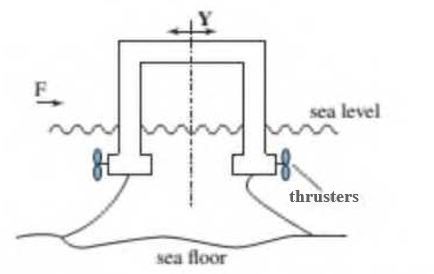
FIGURE Pl.4 Tethered platform using side thrusters for positioning�
Munoz-Mansilla,. R., Aranda, J., Diaz, J. M Chaos, D., and Reinoso, A. J.,
Applications of QFT Robust Control Techniques to Manne Systems. 9th IEEE International Conference on Control and Automation. December 19-21. 2011. pp. 378-385. (Figure 3. p. 382). system is to be designed in which the objective is to minimize the drift. Y, and an angular deviation from the vertical axes. ϕ (not shown). The disturbances acting on the system's outputs are the force. F. and the torque, M, caused by the external environment. In this problem, the plant will have one input, the force delivered by the thrusters (Fu) and two outputs. Y and ϕ. Note also that this is a disturbance attenuation problem, so there is no command input. Draw a block diagram of the system indicating the disturbances F and M. the control signal Fu, and the outputs Y and ϕ. Your diagram should also have blocks for a controller, the one-input two-output plant, and a block indicating how the disturbances affect each of the outputs.
Want to see the full answer?
Check out a sample textbook solution
Chapter 1 Solutions
Control Systems Engineering


- Q3) A. Analyze and discuss the Extension Speed of Controlling Cylinder. 2-One-Way adjustable throttle 4-Single-acting telescopic cylinder B.Draw the symbols of:[ 1-Shuttle valve OR Gate 3-(4/2 DCV) 5- Servo symbols]arrow_forwardA mechanism is composed of the following: Link 1 (AF) - horizontal ground with a length of 7 cm. "A" is on the left side Link 2 (AB) - 2 cm in length. Initially 30 degrees above the x-axis Link 3 (BCD) - tertiary link, BC=DC=2cm, BD=3cm point C lies below line BD Link 4 (CE) - link connecting link 3 to slider link 5 Link 5 (E) - slider moving along the ground positioned 1 cm left of point F Link 6 (DF) Find the velocity of C and E in terms of velocity of B assuming that link 2 rotates counterclockwise.arrow_forwardThe following data are available for a belt conveyor design: 1. Conveyor capacity: = 1300 t/h; 2. Belt speed = 1.5 m/sec; 3. Conveyor height = 15 m; 4. Conveyor length = 175 m; 5. Mass of a set of idlers = 15 kg; 6. Idler spacing = 1.2 m; 7. Load due to belt = 25 kg/m; 8. Inclination angle of the conveyor = 10 deg.; 9. Coefficient of friction = 0.05; 10. Start-up factor = 1.5; 11. Drive efficiency = 0.90; 12. Friction factor = 12; and 13. Breaking strength loss factor = 0.80 Determine the following: (1) Belt tension, (2) Load due to idlers, (3) Minimum motor power; (4) Acceleration of the conveyor belt, and the (5) Belt breaking strength.arrow_forward
- Find the equation of equilibrium system and draw electrical equivalent system using Force- Current Analogy for mechanical the system shown in Fig.6. Note: Assume that the frictions between the masses and the surfaces are not neglected. K ਹ MI JUL ੨੦ ਖ਼ M Xਣ (3arrow_forwardConsider a pneumatic transferring station shown in Figure Q.3, where two cylinders are used to transfer parts from a lower deck to upper deck of conveyors. Cylinder 2A Cylinder 1A Eject (b) Draw the displacement step diagram of the two cylinders. LIR Figure Q.3 The operation can be described by the following steps: Step 1: Cylinder 1A extends. Step 2: Cylinder 2A extends. Step 3: Cylinder 2A retracts. Step 4: Cylinder 1A retracts. Step 5: Repeat Step 1. The limit switches are used to detect the presence of parts on cylinder 1A and to monitor the positions of the piston rod of cylinders. The process will only start when a part is detected on cylinder 1A. (a) Determine the sequence of movements of the two cylinders for Step 1 to 5. (e) Sketch a pneumatic circuit of the system if all the cylinders are of double acting cylinders and all the DCVs are of 4/2 double solenoid valves. (d) Design an electrical circuit diagram using direct control technique to control the transferring process.…arrow_forwardIn this system, there are two mass elements: m₁ and m₂. They are con- nected by a spring. m₁ is also connected to a massless rod, which can rotate at its midpoint. The other end of this massless rod is connected to another massless rod, which is connected to the ground through a spring and a damper. This configuration forms the basis of the system. You may assume small deflections for this problem and that the vertical connections are rigid links. When the coordinates y₁, y2, y are equal to zero, the gravi- tational force on the masses is covered by springs (the system is at its static deflection). Two input forces, fi and f2, are applied on the masses m₁ and m2 respectively. HINT: You should not consider the gravity force in your solution. Your tasks: A Short Answer: Which elements (refer to them by their corresponding constants) can store or possess energy in this system? B Draw the FBD for each mass (one for each of m₁ and m₂. H C Derive the equations of motion for the masses with…arrow_forward
- Q2: The four-bar linkage mechanism O₂ABO4 shown in Figure 2 is driven by link O₂A 604 at w₂ = 45 rad/s (ccw). Link AO₂= 101.6 mm, Link AB = 254 mm, Link Be₂ 304.8 mm and the fixed link O₂O4= 304.8 mm, link AO2= 101.6 mm, link AB = 254 mm, link BQ₂ = 304.8 mm and the fixed link O₂O4= 304.8 mm. and = 120⁰. BO4 Find the followings: 1. Velocity of point C located at the middle of the link AB. 2. Angular velocities of links AB and BO4 A W2 Ө B Figure 2arrow_forwardConsider the motor-less, three link robot below where all the links have the same mass, m, and length, 1, and its base is a distance d from the right column. Its end-effector is attached to a massless collar that slides along on a vertical rail. The collar is attached to the ceiling by a spring. Sketch the FBDs, 1 for each link. Write the constraint equation(s) and calculate the number of DOFs. T darrow_forwardM B. Aarrow_forward
- 2. For the locking pliers (also known as vise grip) shown (Fig. 2) here the link lengths are |AB| = 10, |AC| = 4.25, |CD| = 3.5, |DB| = 8.5 cm.[5] (a) Draw the kinematic diagram showing clearly the ground links and the driving link and calculate the mobility. (b) For the configuration shown, if LABD = 48°, what is the acute angle between links AC and CD. (c) Repeat 2 for when ZABD = 15° and draw this configuration up to scale.arrow_forward2) Block 4 slides in a slot in the fixed piece 1. Axis Q₂ of crank 2 is fixed on 1. Q₂₂A = 1 1/2 in., and AB = 4/1/2 Draw the mechanism, assuming limen- sions for 1, if desired, or use center lines only. Draw the four-bar linkage for this mechanism, properly rotate the linkage Q₂ ABQ400; Name each link, and show the finite and infinite cranks. Frind graphically the two extreme positions of 13, The axis of the pin by which link 3 is attached to the block 4.. Dimension the length of the stroke of B. Ans. 3& in. for scale 1:1arrow_forwardProblem-5: The mass of the stepped disk is m, and centroidal mass moment of inertia, JG. At t = 0, y = 0 and the disk is at rest and in static equilibrium. Taking the value of all constants (m, R, k, c, JG) = 1, find the zero input response if 6(0) = 1 and Odot = w(0) = 0. a) Assume that the centroid, G, translates vertically while the disk rotates; b) the cable does not slip with respect to disk; c) The smaller disk, R is rigidly attached to the larger disk, 2R and both rotates with same angular velocity. G R 2R 0, a wwwarrow_forward
 Elements Of ElectromagneticsMechanical EngineeringISBN:9780190698614Author:Sadiku, Matthew N. O.Publisher:Oxford University Press
 Mechanics of Materials (10th Edition)Mechanical EngineeringISBN:9780134319650Author:Russell C. HibbelerPublisher:PEARSON
 Thermodynamics: An Engineering ApproachMechanical EngineeringISBN:9781259822674Author:Yunus A. Cengel Dr., Michael A. BolesPublisher:McGraw-Hill Education
 Control Systems EngineeringMechanical EngineeringISBN:9781118170519Author:Norman S. NisePublisher:WILEY
 Mechanics of Materials (MindTap Course List)Mechanical EngineeringISBN:9781337093347Author:Barry J. Goodno, James M. GerePublisher:Cengage Learning
 Engineering Mechanics: StaticsMechanical EngineeringISBN:9781118807330Author:James L. Meriam, L. G. Kraige, J. N. BoltonPublisher:WILEY