
Concept explainers
Videos
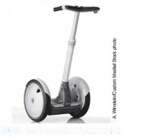
A Segway ®5 Personal Transporter (PT) (Figure Pl .3) is a two-wheeled vehicle in which the human operator stands vertically on a platform. As the driver leans left, right, forward, or backward, a set of sensitive gyroscopic- sensors sense the desired input. These signals are fed to a computer that amplifies them and commands motors to propel the vehicle in the desired direction. One very important feature of the PT is its safety: The system will maintain its vertical position within a specified angle despite road disturbances, such as uphills and downhills or even if the operator over-leans in any direction. Draw a functional block diagram of the PT system that keep The System in a vertical position. Indicate the input and output signals, intermediate signals, and many subsystems. (http://segway.com)
Want to see the full answer?
Check out a sample textbook solution
Chapter 1 Solutions
Control Systems Engineering


- 3.16 [15] Assign link frames to the RPR planar robot shown in Fig. 3.36, and give thelinkage parameters.arrow_forwardA manipulator’s end-effector position is calculated as follows:x = q0 cos q1 + l2 cos(q1 + q2),y = q0 sin q1 + l2 sin(q1 + q2),where q0,1,2 represent joint displacements and l2 is a constant positive parameter.Which of the following describes this manipulator:1) This is a robot-manipulator with 3 revolute joints.2) This is a robot-manipulator with 2 revolute and 1 prismatic joints.3) This is a robot-manipulator with 1 prismatic and 3 revolute joints.4) This is a robot-manipulator with 2 revolute joints. A robot’s end-effector’s tool position is defined asx = L1 cos(q1) + q3 sin(q1 + q2)where L1 = const, q1 = q1(t), q2 = q2(t) and q3 = q3(t) with t defining time. Calculate ∂x / ∂q3 1) it is impossible to calculate as the equation for the y and z positions are missing.2) cos(q1 + q2).3) it is impossible to calculate as time is not given.4) sin(q1 + q2).arrow_forwardsolve by the concepts of ststicsarrow_forward
- 1) A slider-crank mechanism is a planar mechanism that performs a conversion between the translational motion of a slider and the rotational motion of a crank. It is used in many different engineering applications. A familiar example will be a piston engine. In Figure 1, a basic slider- crank mechanism is shown. В b dạc Figure 1. A basic slider-crank mechanism 0< 0< 2n; b = 20 cm; I= 50 cm 1- Find the angle of Ø and the distance of dAC as a function of 0. 2- If crank AB has a rotational speed of w = 1000 rev/min; find velocity of C (Vc) and velocity and acceleration of link BC (vBC & aBC)arrow_forward2. For the locking pliers (also known as vise grip) shown (Fig. 2) here the link lengths are |AB| = 10, |AC| = 4.25, |CD| = 3.5, |DB| = 8.5 cm.[5] (a) Draw the kinematic diagram showing clearly the ground links and the driving link and calculate the mobility. (b) For the configuration shown, if LABD = 48°, what is the acute angle between links AC and CD. (c) Repeat 2 for when ZABD = 15° and draw this configuration up to scale.arrow_forwardAssume you have a 1U cubesat, which has a total mass of 2kg. It has one reaction wheel to control its orientation around its nadir pointing axis. The mass of the reaction wheel is 200g. The wheel itself has a diameter of 30mm and a thickness of 10mm. You may ignore any translational motion for the time being. (a) Write down the kinematic and dynamic equations of the system and compute all relevant constant values. (b) Where do you want to mount your wheel? Make a drawing and a qualitative argument.arrow_forward
- 3. (a) What are the different actuators used for the robotics application? Explain with the help of diagram of a typical speed-torque plot of a DC motor. (b) (i) Write down the five properties for general rotation matrix. (ii) Express the mapping between rotated frames with the help of diagram and justify R' = R" and RR" = 1arrow_forwardTask 1): The quarter-car model of a vehicle suspension and its free body diagram are shown in Figure 1. In this simplified model, the masses of the wheel, tire, and axle are neglected, and the mass m represents one-fourth of the vehicle mass. The spring constant k models the elasticity of both the tire and the suspension spring. The damping constant c models the shock absorber. The equilibrium position of m when y=0 is x=0. The road surface displacement y(t) can be derived from the road surface profile and the car's speed. a) Draw free body diagram (FBD) and derive the equation of motion of m with y(t) as the input, and obtain the transfer function. Body m 1 Suspension Road k Datum level Figure 1 Dynamic Analysis and Control If assume: m=250 kg k=10000, 30000, 50000 N/m c=1000, 2000, 3000 N.s/m b) Plot magnification ratio vs frequency ratio (r=0-4) diagrams for the parameters given above (you can draw the three curves in one diagram for three different k values and do the same for the…arrow_forwardThe position vectors that are defined for kinematic analysis of a mechanism should form one or more kinematic loops also called?arrow_forward
- Weight Ple Figure 4: Schematic of a pile driver f(t) m+bv=f(1) m by 3 X pile Figure 5: First-order model of the pile in soil 5. Figure 4 shows a pile driver that is used to drive piles into soil to provide foundation support for buildings. Two major components of a pile driver are a pile and a weight. The pile is in the form of a long rod going into the soil. The weight is to impact the pile at the top with an impulsive force, thus driving the pile into the soil. Figure 5 shows a first-order model of the pile in the soil. The impulsive force produced by the weight is f(t). The resistance of the soil is modeled via a viscous damping coefficient. b. The weight of the pile is balanced by the normal forces in the soil, so it does not need to be considered. In addition, the elasticity of the soil is ignored. Let z(t) and v(t) be the downward displacement and velocity of the pile, respectively. The equation of motion governing the pile velocity v(t) is dv (5) where m is the mass of the pile.…arrow_forward"The position vectors that are defined for kinematic analysis of a mechanism should form one or more kinematic loops also called Vector Polygon"Vector polygon is wrong so what's the answer? pls help me thanks!arrow_forwardAim: To conduct a full kinematic analysis and calculate dynamic reaction forces in a linkage mechanism, calculate instantaneous torque, required to drive the mechanism and to present the results of the case study in a clear reporting format. Introduction: Figure 1 shows a pumpjack operating at an oil well. Its representation as a linkage is also shown in Figure 1. The pumpjack is driven by a motor attached to crank OA. A constant torque T is applied to the crank and the crank rotates at a constant angular velocity ???. A force P is applied vertically downwards at the end of the walking beam BD, which has its centre of mass at point G. To design the mechanism, a careful kinematic analysis of the mechanism needs to be conducted. To avoid mechanical failure and to provide adequate support to the mechanism, the engineer needs to analyse the reaction forces in the joints. Masses of links OA and AB are assumed to be smaller in comparison with the mass of BD and are ignored in the analysis.…arrow_forward
 Elements Of ElectromagneticsMechanical EngineeringISBN:9780190698614Author:Sadiku, Matthew N. O.Publisher:Oxford University Press
 Mechanics of Materials (10th Edition)Mechanical EngineeringISBN:9780134319650Author:Russell C. HibbelerPublisher:PEARSON
 Thermodynamics: An Engineering ApproachMechanical EngineeringISBN:9781259822674Author:Yunus A. Cengel Dr., Michael A. BolesPublisher:McGraw-Hill Education
 Control Systems EngineeringMechanical EngineeringISBN:9781118170519Author:Norman S. NisePublisher:WILEY
 Mechanics of Materials (MindTap Course List)Mechanical EngineeringISBN:9781337093347Author:Barry J. Goodno, James M. GerePublisher:Cengage Learning
 Engineering Mechanics: StaticsMechanical EngineeringISBN:9781118807330Author:James L. Meriam, L. G. Kraige, J. N. BoltonPublisher:WILEY