
Fundamentals of Electric Circuits
6th Edition
ISBN: 9780078028229
Author: Charles K Alexander, Matthew Sadiku
Publisher: McGraw-Hill Education
expand_more
expand_more
format_list_bulleted
Concept explainers
Videos
Textbook Question
Chapter 9.8, Problem 13PP
Design an RC circuit to provide a 90° lagging phase shift of the output voltage relative to the input voltage. If an ac voltage of 60 V rms is applied, what is the output voltage?
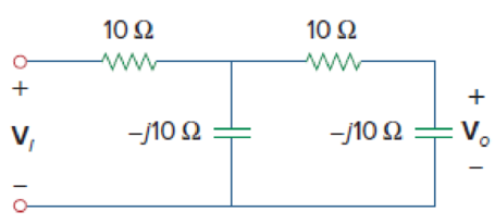
Figure 9.34
Expert Solution & Answer
Want to see the full answer?
Check out a sample textbook solution
Students have asked these similar questions
How do I find the phase of this sinc function?
Problem
Design a circuit to limit a 20 V rms sinusoidal
voltage to a maximum positive amplitude of 10 V
and a maximum negative amplitude of -5 V using
a single 14 V dc voltage source.
Shown in the figure below is an "RL" circuit drive by an AC power source. The AC power source has an RMS voltage of Vps (RMS) = 9.84 Volts and is running at a frequency of f = 8.585e+04 Hz. The resistor has a resistance of R = 2170 and the inductor has an inductance of L = 3.54e-03 Henries.
Vps
R
ww
Write the FORMULA for the total impedance of the circuit Ztot =
Determine the numerical value of Ztot = 2890.5
Determine the numerical value of $z= = 41
Determine the current through the circuit:
• I(PEAK) = 4.81E-3
• I(RMS) = 3.404E-3
Determine the voltage across the resistor:
• VR(PEAK) = 7.387
• VR(RMS) = 5.22
✔✔ Amps
✔Amps
Write the FORMULA for the phase of the total impedance of the circuit z... = | tan-1 2701
R
x Volts
X Volts
Determine the voltage across the inductor:
• VL(PEAK) = 9.184
• VL(RMS) = 6.49
✔ Volts
Volts
L
R²+ WL-
✔ degrees
2
If a second circuit were connected in parallel with the inductor, this circuit would be considered as:
O a low-pass filter
O a capacitive switcher…
Chapter 9 Solutions
Fundamentals of Electric Circuits
Ch. 9.2 - Practice Problem 9.1 Given the sinusoid 45 cos(5t...Ch. 9.2 - Practice Problem 9.2 Find the phase angle between...Ch. 9.3 - Prob. 3PPCh. 9.3 - Express these sinusoids as phasors: (a)...Ch. 9.3 - Find the sinusoids corresponding to these phasors:...Ch. 9.3 - If v1=10sint30V and v2=20cost+45V, find v=v1+v2.Ch. 9.3 - Prob. 7PPCh. 9.4 - If voltage v=25sin100t15V is applied to a 50F...Ch. 9.5 - Refer to Fig. 9.17. Determine v(t) and i(t).Ch. 9.7 - Determine the input impedance of the circuit in...
Ch. 9.7 - Calculate vo in the circuit of Fig. 9.27. Figure...Ch. 9.7 - Find I in the circuit of Fig. 9.30. Figure 9.30Ch. 9.8 - Design an RC circuit to provide a 90 lagging phase...Ch. 9.8 - Refer to the RL circuit in Fig. 9.36. If 10 V is...Ch. 9.8 - In the ac bridge circuit of Fig. 9.37, suppose...Ch. 9 - Which of the following is not a right way to...Ch. 9 - A function that repeats itself after fixed...Ch. 9 - Which of these frequencies has the shorter period?...Ch. 9 - If v1 = 30 sin(t + 10) and v2 = 20 sin(t + 50),...Ch. 9 - The voltage across an inductor leads the current...Ch. 9 - The imaginary part of impedance is called:...Ch. 9 - The impedance of a capacitor increases with...Ch. 9 - At what frequency will the output voltage v0(t) in...Ch. 9 - A series RC circuit has VR = 12 V and VC = 5 V....Ch. 9 - A series RCL circuit has R = 30 , XC = 50 , and XL...Ch. 9 - Given the sinusoidal voltage v(t) = 50 cos (30t +...Ch. 9 - A current source in a linear circuit has...Ch. 9 - Express the following functions in cosine form:...Ch. 9 - Design a problem to help other students better...Ch. 9 - Given v1=45sint+30V and v2=50cost30V, determine...Ch. 9 - For the following pairs of sinusoids, determine...Ch. 9 - If f() = cos + j sin , show that f() = ej.Ch. 9 - Calculate these complex numbers and express your...Ch. 9 - Evaluate the following complex numbers and leave...Ch. 9 - Design a problem to help other students better...Ch. 9 - Find the phasors corresponding to the following...Ch. 9 - Let X=440 and Y=2030. Evaluate the following...Ch. 9 - Evaluate the following complex numbers: (a)...Ch. 9 - Simplify the following expression: (a)...Ch. 9 - Evaluate these determinants: (a) 10+j62j351+j (b)...Ch. 9 - Prob. 16PCh. 9 - Two voltages v1 and v2 appear in series so that...Ch. 9 - Obtain the sinusoids corresponding to each of the...Ch. 9 - Using phasors, find: (a) 3cos20t+105cos20t30 (b)...Ch. 9 - A linear network has a current input 7.5cos10t+30A...Ch. 9 - Simplify the following: (a) ft=5cos2t+154sin2t30...Ch. 9 - An alternating voltage is given by v(t) = 55...Ch. 9 - Apply phasor analysis to evaluate the following:...Ch. 9 - Find v(t) in the following integrodifferential...Ch. 9 - Using phasors, determine i(t) in the following...Ch. 9 - Prob. 26PCh. 9 - A parallel RLC circuit has the node equation...Ch. 9 - Determine the current that flows through an 20-...Ch. 9 - Given that vc(0) = 2 cos(155) V, what is the...Ch. 9 - A voltage v(t) = 100 cos(60t + 20) V is applied to...Ch. 9 - A series RLC circuit has R = 80 , L = 240 mH, and...Ch. 9 - Using Fig. 9.40, design a problem to help other...Ch. 9 - A series RL circuit is connected to a 220-V ac...Ch. 9 - What value of will cause the forced response, vo...Ch. 9 - Find the steady-state current i in the circuit of...Ch. 9 - Using Fig. 9.43, design a problem to help other...Ch. 9 - Determine the admittance Y for the circuit in Fig....Ch. 9 - Using Fig. 9.45, design a problem to help other...Ch. 9 - For the circuit shown in Fig. 9.46, find Zeq and...Ch. 9 - In the circuit of Fig. 9.47, find io when: (a) =...Ch. 9 - Find v(t) in the RLC circuit of Fig. 9.48. Figure...Ch. 9 - Calculate vo(t) in the circuit of Fig. 9.49....Ch. 9 - Find current Io in the circuit shown in Fig. 9.50....Ch. 9 - Calculate i(t) in the circuit of Fig. 9.51. Figure...Ch. 9 - Find current Io in the network of Fig. 9.52....Ch. 9 - If vs = 100 sin(10t + 18) V in the circuit of Fig....Ch. 9 - In the circuit of Fig. 9.54, determine the value...Ch. 9 - Given that vs(t) = 20 sin (100t 40) in Fig. 9.55,...Ch. 9 - Find vs (t) in the circuit of Fig. 9.56 if the...Ch. 9 - Determine vx in the circuit of Fig. 9.57. Let...Ch. 9 - If the voltage vo across the 2- resistor in the...Ch. 9 - If V in the circuit of Fig. 9.59, find Is. Figure...Ch. 9 - Find Io in the circuit of Fig. 9.60.Ch. 9 - In the circuit of Fig. 9.61, Find Vs if Io=300A.Ch. 9 - Find Z in the network of Fig. 9.62, given that...Ch. 9 - At = 377 rad/s, find the input impedance of the...Ch. 9 - At = 1 rad/s, obtain the input admittance in the...Ch. 9 - Using Fig. 9.65, design a problem to help other...Ch. 9 - For the network in Fig. 9.66, find Zin. Let = 100...Ch. 9 - Obtain Zin for the circuit in Fig. 9.67. Figure...Ch. 9 - Find Zeq in the circuit in Fig. 9.68. Figure 9.68Ch. 9 - For the circuit in Fig. 9.69, find the input...Ch. 9 - For the circuit in Fig. 9.70, find the value of...Ch. 9 - Find ZT and Vo in the circuit in Fig. 9.71. Let...Ch. 9 - Determine ZT and I for the circuit in Fig. 9.72....Ch. 9 - For the circuit in Fig. 9.73, calculate ZT and...Ch. 9 - At = 103 rad/s, find the input admittance of each...Ch. 9 - Determine Yeq for the circuit in Fig. 9.75. Figure...Ch. 9 - Find the equivalent admittance Yeq of the circuit...Ch. 9 - Find the equivalent impedance of the circuit in...Ch. 9 - Obtain the equivalent impedance of the circuit in...Ch. 9 - Calculate the value of Zab in the network of Fig....Ch. 9 - Determine the equivalent impedance of the circuit...Ch. 9 - Design an RL circuit to provide a 90 leading phase...Ch. 9 - Design a circuit that will transform a sinusoidal...Ch. 9 - For the following pairs of signals, determine if...Ch. 9 - Refer to the RC circuit in Fig. 9.81. (a)...Ch. 9 - A coil with impedance 8 + j6 is connected in...Ch. 9 - (a) Calculate the phase shift of the circuit in...Ch. 9 - Consider the phase-shifting circuit in Fig. 9.83....Ch. 9 - The ac bridge in Fig. 9.37 is balanced when R1 =...Ch. 9 - A capacitance bridge balances when R1 = 100 , R2 =...Ch. 9 - An inductive bridge balances when R1 = 1.2 k, R2 =...Ch. 9 - The ac bridge shown in Fig. 9.84 is known as a...Ch. 9 - The ac bridge circuit of Fig. 9.85 is called a...Ch. 9 - The circuit shown in Fig. 9.86 is used in a...Ch. 9 - The network in Fig. 9.87 is part of the schematic...Ch. 9 - A series audio circuit is shown in Fig. 9.88. (a)...Ch. 9 - An industrial load is modeled as a series...Ch. 9 - An industrial coil is modeled as a series...Ch. 9 - Figure 9.91 shows a series combination of an...Ch. 9 - A transmission line has a series impedance of and...Ch. 9 - A power transmission system is modeled as shown in...
Additional Engineering Textbook Solutions
Find more solutions based on key concepts
The voltage source of the circuit shown in Fig. P1.29 is given by s(t)=25cos(4104t45)(V). Obtain an expression ...
Fundamentals of Applied Electromagnetics (7th Edition)
Design an ideal inverting op-amp circuit such that the voltage gain is Av=25 . The maximum current in any resis...
Microelectronics: Circuit Analysis and Design
Three point charges of equal magnitude q, that will yield a zero net electric field at the origin.
Engineering Electromagnetics
Find I0 and I1 in the circuit in Fig.P2.12.
Basic Engineering Circuit Analysis
Assume a telephone signal travels through a cable at two-thirds the speed of light. How long does it take the s...
Electric Circuits (10th Edition)
Identify the type of input and output configuration for each diff-amp in Figure 18-35.
Electronics Fundamentals: Circuits, Devices & Applications
Knowledge Booster


Learn more about
Need a deep-dive on the concept behind this application? Look no further. Learn more about this topic, electrical-engineering and related others by exploring similar questions and additional content below.Similar questions
- The peak to peak distance of a sinusoidal waveform displayed on a C.R.O. screen is 9 cm and the 'volts/cm' switch is on 45 V/cm. The peak voltage is given by 405.00 V 202.50 V 5.00 V O 286.33 Varrow_forward7 Find the average and effective values of voltage for sinusoidal waveform shown in Figure. Vm = 100 V 2x x14 9714 [Ans: 27.17 V, 47. 67 V]arrow_forwardDetermine the rms current in the figure for Vrms = 16 V and C = 74µF V f=10 kHzarrow_forward
- For the below sinusoidal voltage trace displayed by the CRO, the time/cm switch is on 0.2ms/cm and the volt/cm switch is on 1 V/cm. a) the frequency will be Hz b) the r.m.s value will be In CRO the beam can also be shifted vertically by applving a suitable DC voltage to thearrow_forwardDesign a circuit to limit a 20 V rms sinusoidal voltage to a maximum positive amplitude of 10 V and a maximum negative amplitude of using a single 14 V dc voltage source.arrow_forwardIn an experiment, the function generator is adjusted to generate a square voltage at a certain frequency. This voltage is displayed on an oscilloscope and the reading is 16 V peak-to-peak. The rms value of this voltage is .What will be the rms value of this voltage if the frequency is doubled? Select one: O 16 Vrms 32 Vrms O 8 Vrms . 8 Vrms ..... O 5.657 Vrms 5.657 Vrms ....... O 8 Vrms . 16 Vrms O 16 Vrms 8 Vrms ......arrow_forward
- Determine and sketch the output voltage waveform for the circuit shown if the sinusoidal signal at the input has a peak-to-peak voltage of 30 volts with V=5volts. Identify the circuit.arrow_forwardShown in the figure below is an "RC" circuit drive by an AC power source. The AC power source has an RMS voltage of Vps (RMS) = 11.58 Volts and is running at a frequency of f = 1.326e+04 Hz. resistor has a resistance of R = 3750 2 and the capacitor has an capacitance of C = 3.17e-09 Farads. Vps R ww Write the FORMULA for the total impedance of the circuit Ztot = Write the FORMULA for the phase of the total impedance of the circuit tot = Determine the numerical value of Ztot = Determine the numerical value of Pztot= Determine the current through the circuit: • I(PEAK) = • I(RMS) = Determine the voltage across the resistor: Amps Amps S2 C degreesarrow_forwardC5 What is the correct explanation for the voltage seen at Va in Figure C5? Va 1 Sost We will assume that the Vout Out Vb, capacitor is charged to a value determined by the feedback and the supply voltage +BVsat. Figure C5 A. The waveform on the capacitor looks like a discharge, and then a charging waveform to an equal but opposite magnitude voltage, B. The capacitor simply reverses its charge, with a charging waveform, C. The capacitor simply reverses its charge, with a discharging waveform, D. None of the above.arrow_forward
- A sinusoidal waveform is displayed on a C.R.O. screen, the time/cm switch is on 30 µs/cm and the volt/cm switch is on 20 V/cm. The width of one complete cycle is 3.8 cm and the peak to peak distance is 4.8 cm. Determine the following: The frequency is? The magnitude of the sine voltage is? The amplitude is? The R.M.S voltage is?arrow_forwardThe peak distance of a sinusoidal waveform displayed on a C.R.O. screen is 11 cm and the 'volts/cm' switch is on 38 V/cm. The peak to peak voltage is given by O 3.45 V 295.53 V 836.00 V O 209.00 Varrow_forwardWrite the general voltage equation for a 250-Hz source whose peak voltage is 300 V.arrow_forward
arrow_back_ios
SEE MORE QUESTIONS
arrow_forward_ios
Recommended textbooks for you
 Introductory Circuit Analysis (13th Edition)Electrical EngineeringISBN:9780133923605Author:Robert L. BoylestadPublisher:PEARSON
 Delmar's Standard Textbook Of ElectricityElectrical EngineeringISBN:9781337900348Author:Stephen L. HermanPublisher:Cengage Learning
 Programmable Logic ControllersElectrical EngineeringISBN:9780073373843Author:Frank D. PetruzellaPublisher:McGraw-Hill Education
 Fundamentals of Electric CircuitsElectrical EngineeringISBN:9780078028229Author:Charles K Alexander, Matthew SadikuPublisher:McGraw-Hill Education
 Electric Circuits. (11th Edition)Electrical EngineeringISBN:9780134746968Author:James W. Nilsson, Susan RiedelPublisher:PEARSON
 Engineering ElectromagneticsElectrical EngineeringISBN:9780078028151Author:Hayt, William H. (william Hart), Jr, BUCK, John A.Publisher:Mcgraw-hill Education,
Introductory Circuit Analysis (13th Edition)
Electrical Engineering
ISBN:9780133923605
Author:Robert L. Boylestad
Publisher:PEARSON
Delmar's Standard Textbook Of Electricity
Electrical Engineering
ISBN:9781337900348
Author:Stephen L. Herman
Publisher:Cengage Learning
Programmable Logic Controllers
Electrical Engineering
ISBN:9780073373843
Author:Frank D. Petruzella
Publisher:McGraw-Hill Education
Fundamentals of Electric Circuits
Electrical Engineering
ISBN:9780078028229
Author:Charles K Alexander, Matthew Sadiku
Publisher:McGraw-Hill Education
Electric Circuits. (11th Edition)
Electrical Engineering
ISBN:9780134746968
Author:James W. Nilsson, Susan Riedel
Publisher:PEARSON
Engineering Electromagnetics
Electrical Engineering
ISBN:9780078028151
Author:Hayt, William H. (william Hart), Jr, BUCK, John A.
Publisher:Mcgraw-hill Education,
Why HIGH VOLTAGE DC power Transmission; Author: ElectroBOOM;https://www.youtube.com/watch?v=DFQG9kuXSxg;License: Standard Youtube License