
Videos
At ω = 103 rad/s, find the input admittance of each of the circuits in Fig. 9.74.
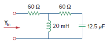
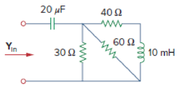
Figure 9.74
(a)
Find the value of input admittance
Answer to Problem 67P
The value of input admittance
Explanation of Solution
Given data:
Refer to Figure 9.74(a) in the textbook.
The value of angular frequency
Formula used:
Write a general expression to calculate the impedance of a resistor.
Here,
Write a general expression to calculate the impedance of an inductor.
Here,
Write a general expression to calculate the impedance of a capacitor.
Here,
Write a general expression to calculate the input admittance.
Here,
Calculation:
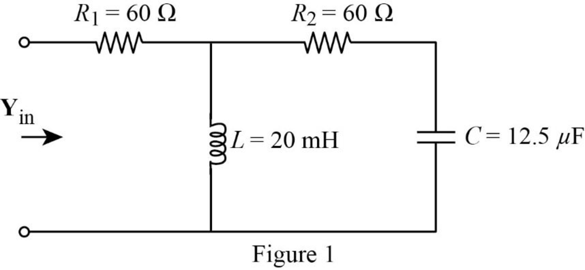
The given circuit is redrawn as shown in Figure 1.
Use equation (1) to find
Use equation (1) to find
Substitute
Substitute
The impedance diagram of Figure 1 is drawn as shown in Figure 2.
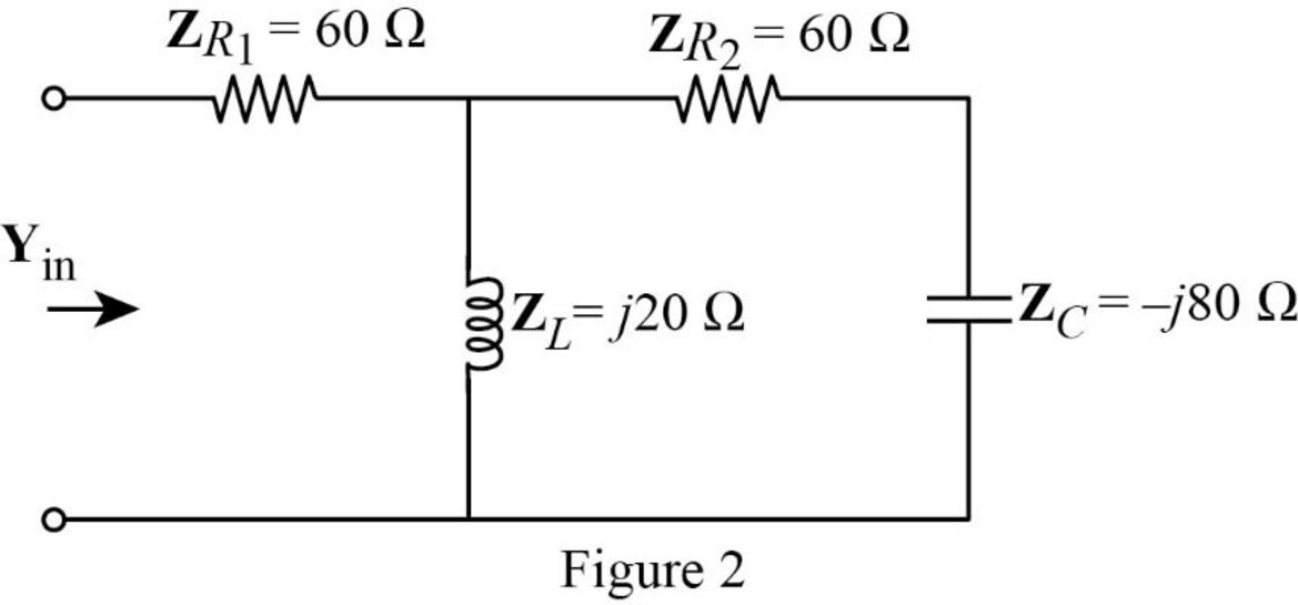
Refer to Figure 2, the impedance
The input impedance
Substitute
Conclusion:
Thus, the value of input admittance
(b)
Find the value of input admittance
Answer to Problem 67P
The value of input admittance
Explanation of Solution
Calculation:
The given circuit is also redrawn as shown in Figure 3.
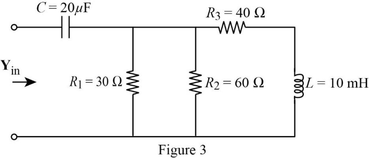
Use equation (1) to find
Use equation (1) to find
Use equation (1) to find
Substitute
Substitute
The impedance diagram of Figure 3 is drawn as shown in Figure 4.
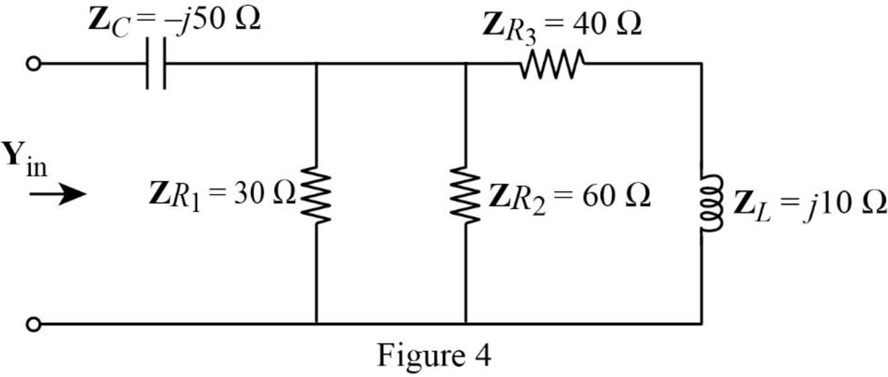
Refer to Figure 4, the impedances
The equivalent impedance
Now, the Figure 4 is reduced as shown in Figure 5.
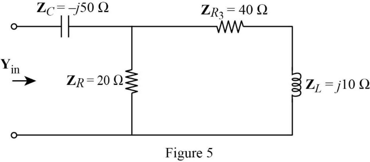
Refer to Figure 5, the impedance
The input impedance
Substitute
Conclusion:
Thus, the value of input admittance
Want to see more full solutions like this?
Chapter 9 Solutions
Fundamentals of Electric Circuits
Additional Engineering Textbook Solutions
Loose Leaf for Engineering Circuit Analysis Format: Loose-leaf
Microelectronics: Circuit Analysis and Design
Fundamentals of Applied Electromagnetics (7th Edition)
Principles and Applications of Electrical Engineering
ANALYSIS+DESIGN OF LINEAR CIRCUITS(LL)
Electrical Engineering: Principles & Applications (7th Edition)


- Use Euler's formula to simplify: cos(1+i). ..arrow_forwardFor the following circuit, use phasor-impedance techniques to find the current through the inductor 6 cos 2t A 0.5 H 10 H 1/2 F 592 www THEarrow_forwardLet Zeq be the equivalent impedance of a parallel connection of an inductor with inductance L and a capacitor with capacitance C. At w=1/√√LC, the equivalent impedance is given by O a. Zeq = 0 b. Zeq = 1 O c. Zeq = 00 O d. Zeq = 0.5arrow_forward
- A series circuit consists of a 20-ohm resistance, a 150 mH inductance and an unknown capacitance. The circuit is supplied with a voltage v = 100 sin 314t. Find the value of capacitance at resonancearrow_forwardA given impedance draws 5 A from a 120 V, 60 Hz source. The current through the impedance lags the voltage across it by 60°. What is the total current drawn from the source when 100 µF capacitor is connected in parallel with the given impedance?arrow_forwardA 116 Ω resistor and an unknown capacitor are connectedin series to an ac source with angular frequency 5.10 * 10^3 rad/s. Theamplitude of the resistor voltage is 2.45 V, and the current in the circuithas its maximum positive value at t = 0. Find the capacitancearrow_forward
- An RLC series circuit has an impedance of 60 Ω and a power factor of 0.50, with the voltage lagging the current. (a) Should a capacitor or an inductor be placed in series with the elements to raise the power factor of the circuit?(b) What is the value of the capacitance or self-inductance that will raise the power factor to unity?arrow_forwardThe equivalent capacitance at terminals a-b in the circuit given is 30 F, then the value of C is Choose correct answer A) 15.98 F B) 0.015 F C) 0.062 F D) 6.2 mFarrow_forwardA coil with impedance 8 + j6 is connected in series with a capacitive reactance X. The series combination is connected in parallel with a resistor R. Given that the equivalent impedance of the resulting circuit is 2 ≤ 0° №, find the value of R and X. The value of R= Q and X= Ω.arrow_forward
- A series RC with R = 91-Ω and C =7-F connected across a 100 VDC source for a LONG TIME, what is the voltage across the capacitor? Write the values only (round to four decimal places).arrow_forwardeeeeee t=0 Y. Co) = 15V Ye C4) 0,25MF R In the above circuit, thie switch closes at t= 0. The capacitor is charged to voltage ISV initially. Find the capacitor for the following cases: Ca) R= 8.5k (6) R= 4k () R= 1k * plot the waveforms for each Cuse wwwarrow_forwardI VY O non-sinusoidal... -> For the circuit shown below calculate the output voltage Vo(t). v(t)=cos(t)+2cos (2t)arrow_forward
 Delmar's Standard Textbook Of ElectricityElectrical EngineeringISBN:9781337900348Author:Stephen L. HermanPublisher:Cengage Learning