
Videos
The ac bridge shown in Fig. 9.84 is known as a Maxwell bridge and is used for accurate measurement of inductance and resistance of a coil in terms of a standard capacitance Cs. Show that when the bridge is balanced,
Lx = R2R3Cs and
Find Lx and Rx for R1 = 40 kΩ, R2 = 1.6 kΩ, R3 = 4 kΩ, and Cs = 0.45 μF.
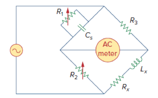
Figure 9.84
Show that when the bridge in Figure 9.85 is balanced the value of resistor
Answer to Problem 84P
The value of resistor
Explanation of Solution
Given data:
Refer to Figure 9.85 in the textbook.
The value of resistor
The value of resistor
The value of resistor
The value of capacitor
Formula used:
Write a general expression to calculate the impedance of a resistor.
Here,
Write a general expression to calculate the impedance of an inductor.
Here,
Write a general expression to calculate the impedance of a capacitor.
Here,
Calculation:
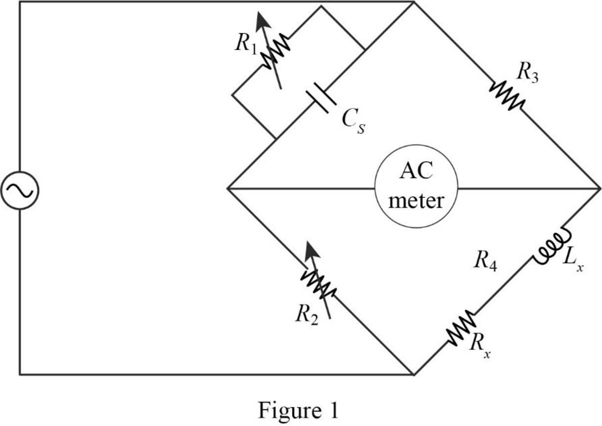
The given circuit is redrawn as shown in Figure 1.
Use equation (1) to find
Use equation (2) to find
Use equation (3) to find
Now, the impedance diagram of Figure 1 is drawn as shown in Figure 2.
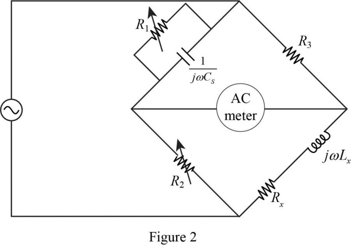
Refer to Figure 2, the impedance of resistor
Therefore, the equivalent impedance
Refer to Figure 2, the impedance of resistor
The equivalent impedance
Let,
The balance of equation of an ac bridge is,
Substitute
Equate the real and imaginary part in above equation.
Simplify the equation (5) to find
Substitute
Substitute
Conclusion:
Thus, when the bridge is balanced, the value of resistor
Want to see more full solutions like this?
Chapter 9 Solutions
Fundamentals of Electric Circuits


- Inductive Circuits Fill in all the missing values. Refer to the following formulas: XL=2fLL=XL2ff=XL2L Inductance (H) Frequency (Hz) Inductive Reactance ( ) 1.2 60 0.085 213.628 1000 4712.389 0.65 600 3.6 678.584 25 411.459 0.5 60 0.85 6408.849 20 201.062 0.45 400 4.8 2412.743 1000 40.841arrow_forwardProblem 2: Determine the voltages across the wo capacitors and the currents through the two inductors under dc conditions. 55 32H C1 =2pF R1 w 1000 R2 www 500 C2 HI 1μF R3 www 300 Den L2 5H R4 900arrow_forward152130 222 Ⓒ520° Fj² 7 Find voltage drop Mutual inductance Majt = + {1.2 V. on 12 resistance Nex (the same for allarrow_forward
- For the circuit shown, fill in the ff. table with its appropriate values. Show complete solution. C2 4uF ci ZuF C4 10uF C3 6uF 600 v CAPACITANCE VOLTAGE CHARGE ENERGY C1 = 2 uF C2 = 4 uF C3 = 6 uF C4 = 10 uF CT = VT = 600 V Qt = ET =arrow_forwardThe picture shows three LC circuits, two of them with capacitors of capacitance C and the three with coils of inductance L, the three circuits are coupled by means of two capacitors Cc capacitors.L inductance coils, the three circuits are coupled by means of two capacitors of capacitance Cc. The currentscirculating through each mesh are those indicated in the figure: I1, I2 and I3. Using Kirchhoff's law for voltagesand taking into account the definition of current I = -dQ/dt, find the system of coupled equations for the systemand then find the angular normal frequencies of the system.arrow_forwardFind equivalent capacitance for the following: a) C1 AHHHH C2 C3 C4 1µF 2µF 3uF 4µF b) C5 C9 1pF C6 2µF C10 3µF C7 4uF C11 5uF C8 6uF C12 A 7uF 8uF C29 с30 С35 C36 С37 С38 HHHH A С39 C32 42µF 42µF 1µF 2uF 3µF 4uF SuF 10μF C40 C31 C33 6pF 9uF C41 C34 ZuF 10μF C42 C43 8pF 8pF B. HHHHHarrow_forward
- 6) When the frequency of an a.c. circuit containing resistance and capacitance is decreased, the current (a) decreases (b) increases (c) stays the same 7) In a series a.c. circuit the voltage across a pure inductance is 12 V and the voltage across a pure resistance is 5 V. The supply voltage is (a) 13 V (b) 17 V (c) 7 V (d) 2.4 V 8) The impedance of a coil, which has a resistance of X ohms and an inductance of Y henrys, connected across a supply of frequency K Hz, is (a) 2π Κ Υ (b) X + Y (c) √x² + y² (d) √X² + (2nKY)² 9) When a capacitor is connected to an a.c. supply the current (a) leads the voltage by 180° (c) leads the voltage by 1/2 rad (b) is in phase with the voltage (d) lags the voltage by 90° 10) In an R-L-C series a.c. circuit a current of 5 A flows when the supply voltage is 100 V. The phase angle between current and voltage is 60° lagging. Which of the following statements is false? (a) The circuit is effectively inductive (c) The equivalent circuit reactance is 25 2 (b)…arrow_forwardDevelop relation for unknown capacitance Cx and Unknown Resistance Rx for the AC Bridge circuit under the balanced condition Cx Rx nullarrow_forward6) When the frequency of an a.c. circuit containing resistance and capacitance is decreased, the current (a) decreases (b) increases (c) stays the same 7) In a series a.c. circuit the voltage across a pure inductance is 12 V and the voltage across a pure resistance is 5 V. The supply voltage is (a) 13 V (b) 17 V (c) 7 V (d) 2.4 V 8) The impedance of a coil, which has a resistance of X ohms and an inductance of Y henrys, connected across a supply of frequency K Hz, is (a) 2π Κ Υ (b) X + Y (c) √x² + y² (d) X² + (2nKY)²arrow_forward
- Q1. Solve for the equivalent capacitance if C1 = 26 micro Farad and C2 = 69 micro Farad. Note: All capacitance are in microfarad. Q2. Solve for the equivalent inductance at terminals a-b, if L1 = 12 mH and L2 = 43 mH. (Hint: You may add wires and flip the circuit) *Pls show the whole solution of these two questions thank you!arrow_forward9. Recall that Kirchhoff's laws help to get the current in circuits. Consider the following circuit: L R I(t) C +q(t) -q(t) Ignore the alternating power for this problem. a) What is the voltage over the resistor if it has a resistance of R ohms and the current is I ampere? b) What is the voltage over the capacitor if the capacitance is C and the charge on the capacitor is q. c) What is the voltage over the inductor if it has an inductance of L Henry? The answer must be in a form of a differential equation.arrow_forwardFind the voltage across the capacitors in the given circuit under dc conditions, where R₁ = 67 Q and R₂ = 17 Q. 1092 R₁ www C₁ +51 - www 50 92 R₂ 60 V The voltage across the capacitors are v₁ = 1 + 22 HH C₂ V and v25 V.arrow_forward
 Delmar's Standard Textbook Of ElectricityElectrical EngineeringISBN:9781337900348Author:Stephen L. HermanPublisher:Cengage Learning