
Concept explainers
Videos
(a) Using the superposition theorem, determine the current through the 12
b. Convert both voltage sources to current sources and recalculate the current to the 12
c. How do the results of parts (a) and (b) compare?
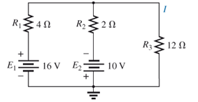
Fig. 9.125
(a)
The current through
Answer to Problem 1P
The current through
Explanation of Solution
Given:
The resistors values are
The voltage sources are
Concept Used:
Elements in the series have the same current.
Elements in the parallels have the same voltage.
Superposition theorem states that in any linear bilateral network having more than one source response in any one of the branches is equal to algebraic sum of the responses caused by individual source while rest of the sources are replaced by their internal impedances.
Short circuit the voltage source and open circuit the current source.
If the resistors are in series, then the value of the equivalent resistance for N series resistors is
If the resistors are in parallel, then the value of the equivalent resistance for N series resistors is
The special case for only two parallel resistors is
Current:
Current division is used to express the current across one of several parallel resistors in terms of current across the combination:
If there are two resistors in parallel then the current across second resistor is
Calculation:
Firstly, short circuit the voltage source
Conclusion:
Hence, the current through
(b)
The current through
Answer to Problem 1P
The current through
Explanation of Solution
Given:
The resistors values are
The voltage sources are
Concept Used:
Elements in the series have the same current.
Elements in the parallels have the same voltage.
Superposition theorem states that in any linear bilateral network having more than one source response in any one of the branches is equal to algebraic sum of the responses caused by individual source while rest of the sources are replaced by their internal impedances.
Short circuit the voltage source and open circuit the current source.
If the resistors are in series, then the value of the equivalent resistance for N series resistors is
If the resistors are in parallel, then the value of the equivalent resistance for N series resistors is
The special case for only two parallel resistors is
Current:
Current division is used to express the current across one of several parallel resistors in terms of current across the combination:
If there are two resistors in parallel then the current across second resistor is
Calculation:
Conclusion:
Hence, the current through
(c)
Compare the results of both the part (a) and (b).
Answer to Problem 1P
The results are similar in both the part (a) and (b).
Explanation of Solution
Given:
The resistors values are
The voltage sources are
Concept Used:
Elements in the series have the same current.
Elements in the parallels have the same voltage.
Superposition theorem states that in any linear bilateral network having more than one source response in any one of the branches is equal to algebraic sum of the responses caused by individual source while rest of the sources are replaced by their internal impedances.
Short circuit the voltage source and open circuit the current source.
Calculation:
The results are similar in both the part (a) and (b).
Conclusion:
Hence, the results are similar in both the part (a) and (b).
Want to see more full solutions like this?
Chapter 9 Solutions
Introductory Circuit Analysis (13th Edition)
Additional Engineering Textbook Solutions
Fundamentals of Applied Electromagnetics (7th Edition)
Electrical Engineering: Principles & Applications (7th Edition)
Applied Statics and Strength of Materials (6th Edition)
C++ How to Program (10th Edition)
Problem Solving with C++ (10th Edition)
Software Engineering (10th Edition)


- d) Terminal A is negative with respect to ter- minals C and D. TEST YOUR KNOWLEDGE Refer to the voltage divider circuit shown in Fig. 9-3. The source voltage is 100Vde and the ammeter indicates a current of .02Ade. Resistor R, is 3000 ohms and the voltage Ec.p between 1. terminals C and D is (30Vdc. Calculate the following: 3. Refer to Fig. 9-1. If the value of resistor Rs was changed to 6.5 kilohms, calculate the following: a) R, = b) E4-5 " Vdc circuit current I c) Eg.c =. Vde d) R; = mAde I=.02 A Vdc 30y de Oc 100vde Vdc Vdc Fig. 9-3 4. The sum of the voltage drops in a series circuit is equal to 2. State whether the following statements regarding Fig. 9-3 are true or false. a) Terminal B is negative with respect to ter- 5. State the algebraic form of Kirchhoff's Law minal A. b) Terminal C is positive with respect to ter- minal B. c) A voltmeter connected between terminals A and C would measure 40Vde,arrow_forwardHW 1- a. For the network of Fig. 9.136. determine the value of R for maximum power to R. b. Determine the maximum power to R. R1 5 A R c. Plot a curve of power to R versus R for R equal to . E 24 T 1. 1 1-, 1 and 2 times the value obtained in part (a). FIG. 9.136arrow_forward4. Find the total equivalent Resistance (Rab). 612 22 30 952 52arrow_forward
- HW • 1- a. For the network of Fig. 9.136, determine the value of R for maximum power to R b. Determine the maximum power to R. c. Plot a curve of power to R versus R for R equal to . R40 SA R4 24 V 1. 1 1 1 and 2 times the value obtained in part (a). FIG. 9.136arrow_forward22. a. Find the Norton equivalent circuit for the network externalto the resistor R in Fig. 9.133.b. Convert the Norton equivalent circuit to the Thévenin form.c. Find the Thévenin equivalent circuit using the Théveninapproach and compare results with part (b)arrow_forwardHW • 1- a. For the network of Fig. 9.136, determine the value of R for maximum power to R. b. Determine the maximum power to R. c. Plot a curve of power to R versus R for R equal to . 1. 14, 14. 14, and 2 times the value obtained in part (a). SA R40 R 24 V FIG. 9.136 *4.75 For the circuit in Fig. 4.141, determine the value of R such that the maximum power delivered to the load is 3 mw. R R ww- R ww IV II wwarrow_forward
- 7. Find the Thévenin equivalent circuit for the network external to the resistor R in each of the networks of Fig. 9.129. R 2.2 k2 ET - 72 V 6ΩΕ- 18 V 5.6 kn 8 mA 16 V (b)arrow_forward21. For each network of Fig. 9.130, find the value of R for maximum power to R, and determine the maximum power to R for each network. 10Ω 60 20 ЗА 25 1 72 V 20 V- 30 in (b) FIG. 9.130arrow_forwardUsing the Millman’s theorem, find the current through and voltage across the resistor RL of Fig. 9.144arrow_forward
- 4. Find the total equivalent Resistance (Rab). 652 212 12 barrow_forward*16. a. Determine the Thevénin equivalent circuit for the net- work external to the resistor R in Fig. 9.140. b. Find the current through the resistor R if its value is 20 Ω, 50 Ω, and 100 Ω c. Without having the Thévenin equivalent circuit, what would you have to do to find the current through the resistor R for all the values of part (b)? R1 R3 R5 20 Ω 12 N 20 E 20 V R2 R4 16 N R FIG. 9.140arrow_forward9. (a) Find the Thevenin equivalent of the circuit shown to the left of terminals a and b. (b) Use the Thevenin equivalent circuit to find the power absorbed by a load resistor of 2 2. (c) Determine the value of R₁ that would absorb the maximum amount of power and find this power. 24 V 30 on 40arrow_forward
 Introductory Circuit Analysis (13th Edition)Electrical EngineeringISBN:9780133923605Author:Robert L. BoylestadPublisher:PEARSON
 Delmar's Standard Textbook Of ElectricityElectrical EngineeringISBN:9781337900348Author:Stephen L. HermanPublisher:Cengage Learning
 Programmable Logic ControllersElectrical EngineeringISBN:9780073373843Author:Frank D. PetruzellaPublisher:McGraw-Hill Education
 Fundamentals of Electric CircuitsElectrical EngineeringISBN:9780078028229Author:Charles K Alexander, Matthew SadikuPublisher:McGraw-Hill Education
 Electric Circuits. (11th Edition)Electrical EngineeringISBN:9780134746968Author:James W. Nilsson, Susan RiedelPublisher:PEARSON
 Engineering ElectromagneticsElectrical EngineeringISBN:9780078028151Author:Hayt, William H. (william Hart), Jr, BUCK, John A.Publisher:Mcgraw-hill Education,