
Concept explainers
Videos
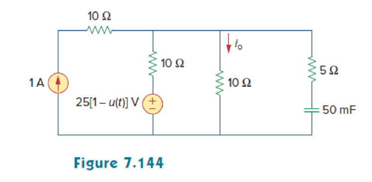
In the circuit of Fig. 7.144, find the value of io for all values of 0 < t.
Find the current
Answer to Problem 80P
The current
Explanation of Solution
Given data:
Refer to Figure 7.144 in the textbook.
The value of capacitance
The source voltage
The current source
Formula used:
Write the general expression to find the complete voltage response for an RC circuit.
Here,
Write the expression to find the time constant for an RC circuit.
Here,
C is the capacitance of the capacitor.
Write the general expression for the unit step function.
Calculation:
The given source voltage is,
Apply the unit step function in equation (3) to equation (4).
For
The given Figure 7.144 is redrawn as shown in Figure 1.
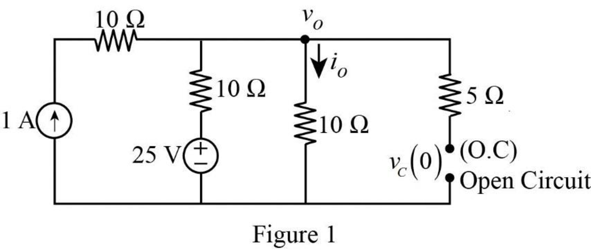
In Figure 1, the capacitor reaches steady state and it will acts as an open circuit. The initial voltage across the capacitor is denoted by
Apply Kirchhoff’s current law at node
Rearrange the equation as follows,
In Figure 1, the initial voltage across the capacitor
For
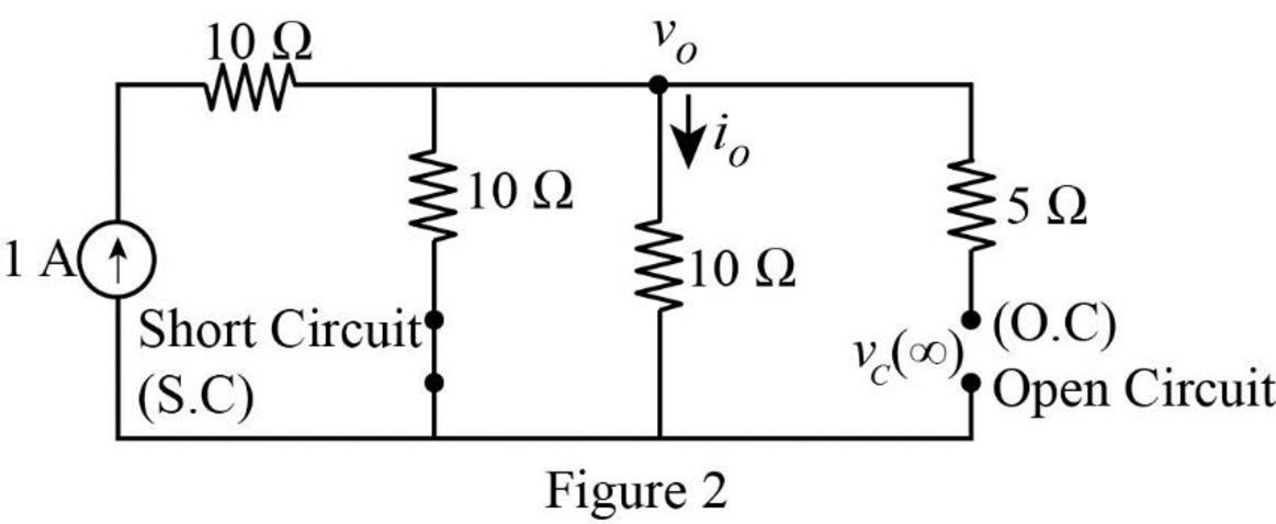
In Figure 2, the voltage source is equal to zero (or a short circuit). Now, the final voltage across the capacitor is represented by
Apply Kirchhoff’s current law at node
Rearrange the equation as follows,
In Figure 2, the final voltage across the capacitor
Figure 3 shows the Thevenin resistance at the capacitor terminal.
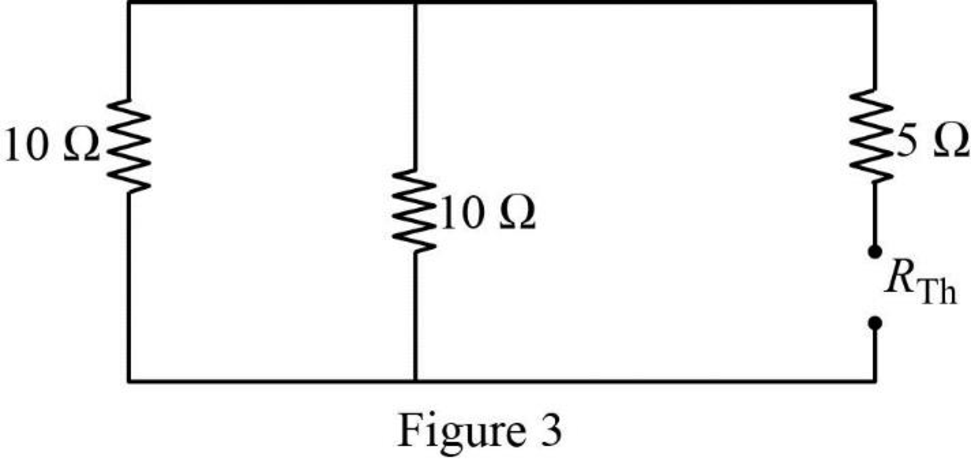
In Figure 3, the Thevenin resistance is calculated as follows.
Substitute
Substitute the units
Substitute
Figure 4 shows the modified circuit diagram.
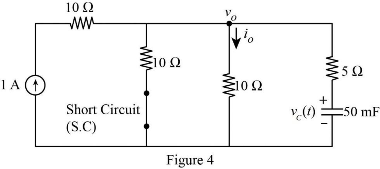
Apply Kirchhoff’s current law at node
Substitute
Reduce the equation as follows,
Therefore, the current
Substitute
Convert the unit A to mA.
Apply the unit step function in equation (3) to equation (6).
PSpice Simulation:
For
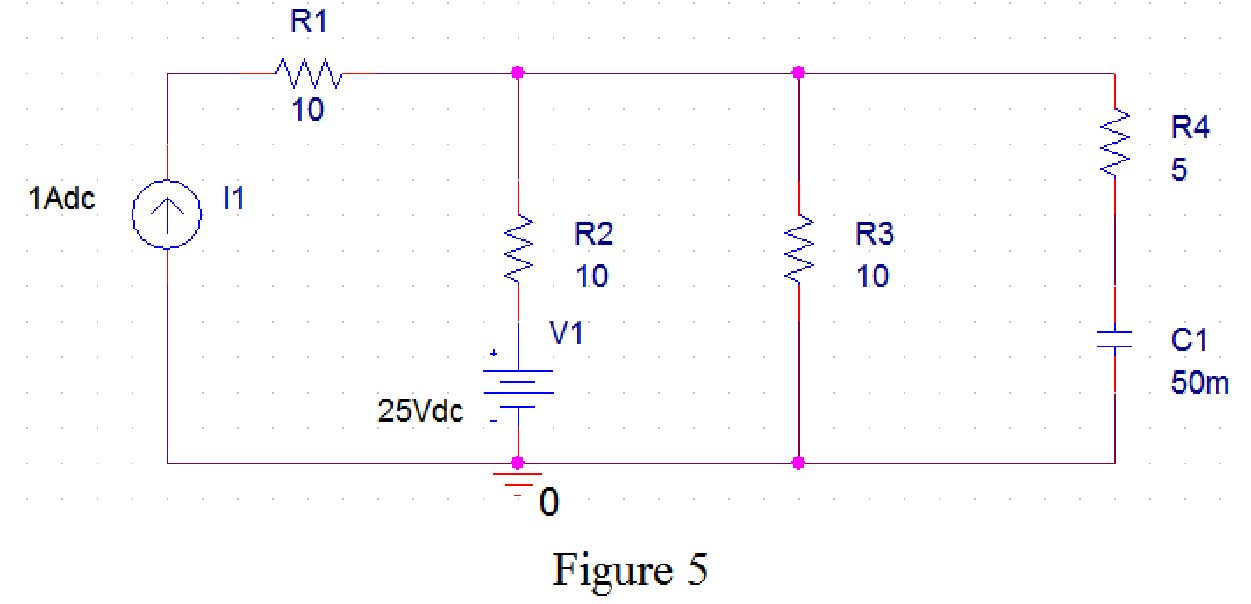
Draw the circuit diagram in PSpice as shown in Figure 5.
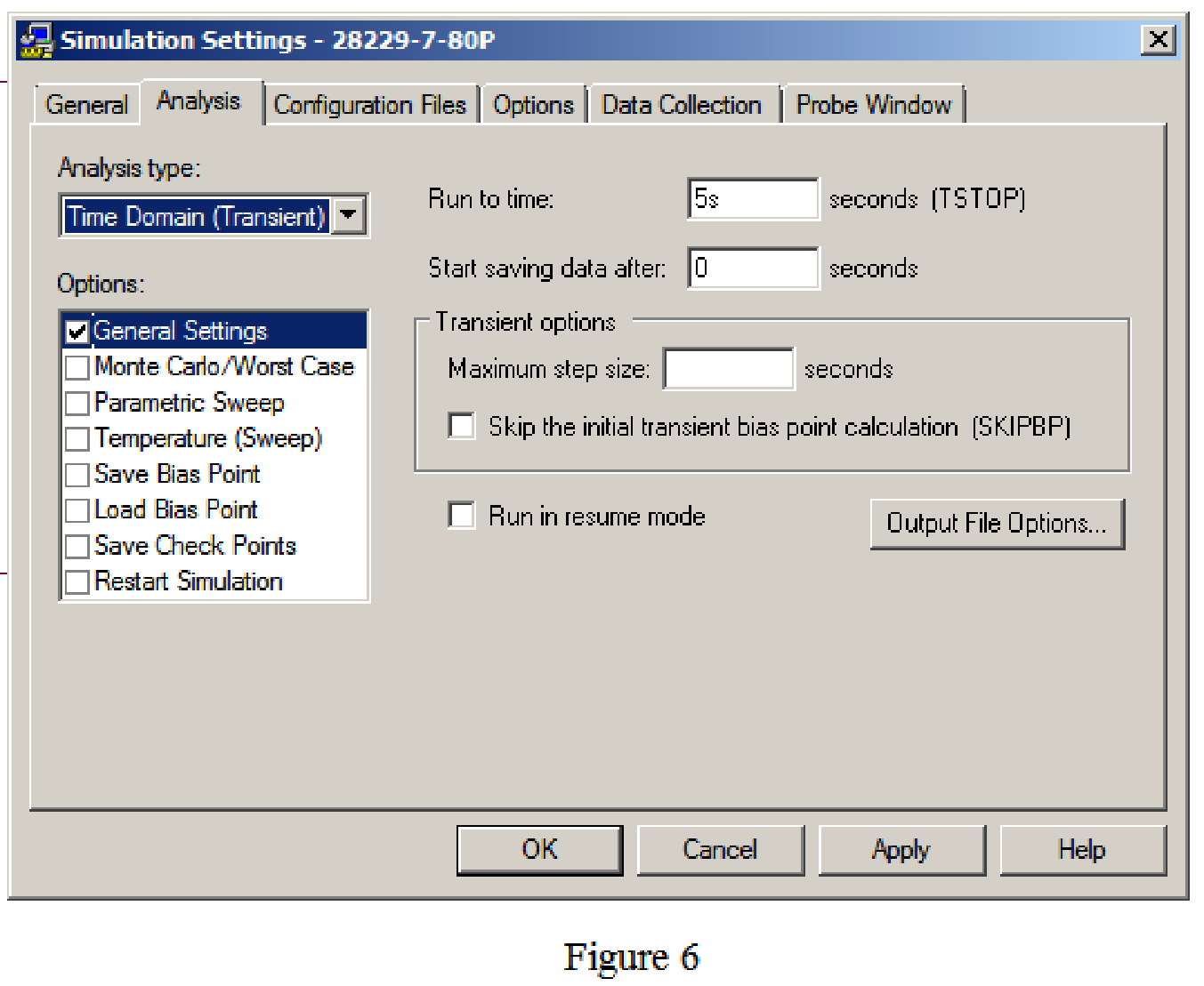
Save the circuit and provide the Simulation Settings as shown in Figure 6.
Now run the simulation and the results will be displayed as shown in Figure 7 by enabling “Enable Bias Voltage Display” icon.
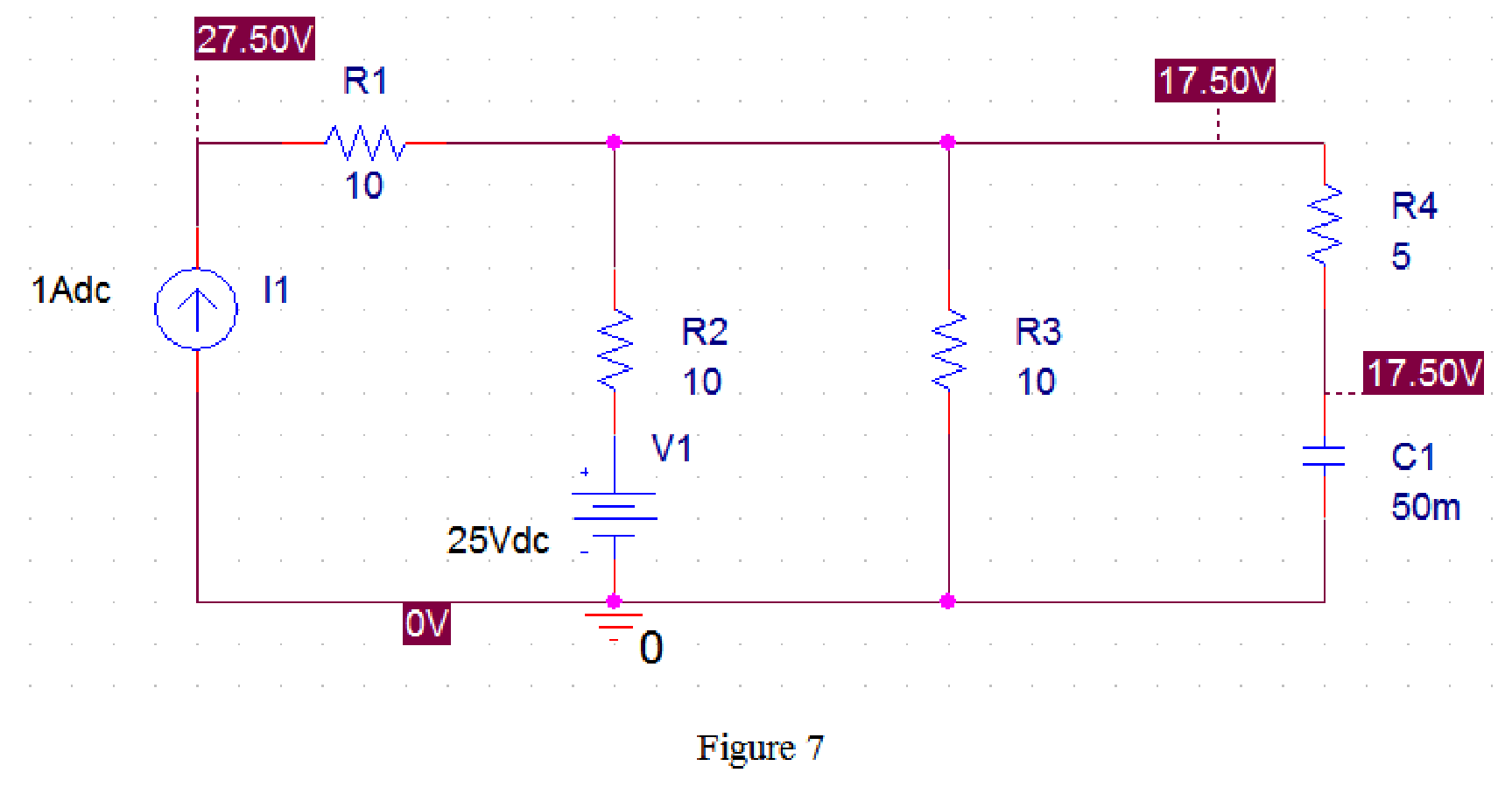
From Figure 7, the initial voltage across the capacitor is 17.5 V.
For
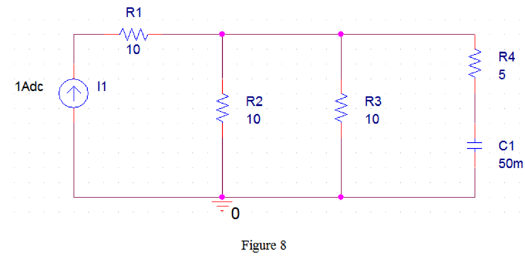
Draw the circuit diagram in PSpice as shown in Figure 8.
Now run the simulation and the results will be displayed as shown in Figure 8 by enabling “Enable Bias Voltage Display” icon.
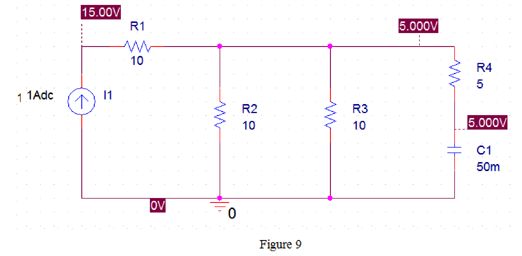
From Figure 9, the final voltage across the capacitor is 5 V.
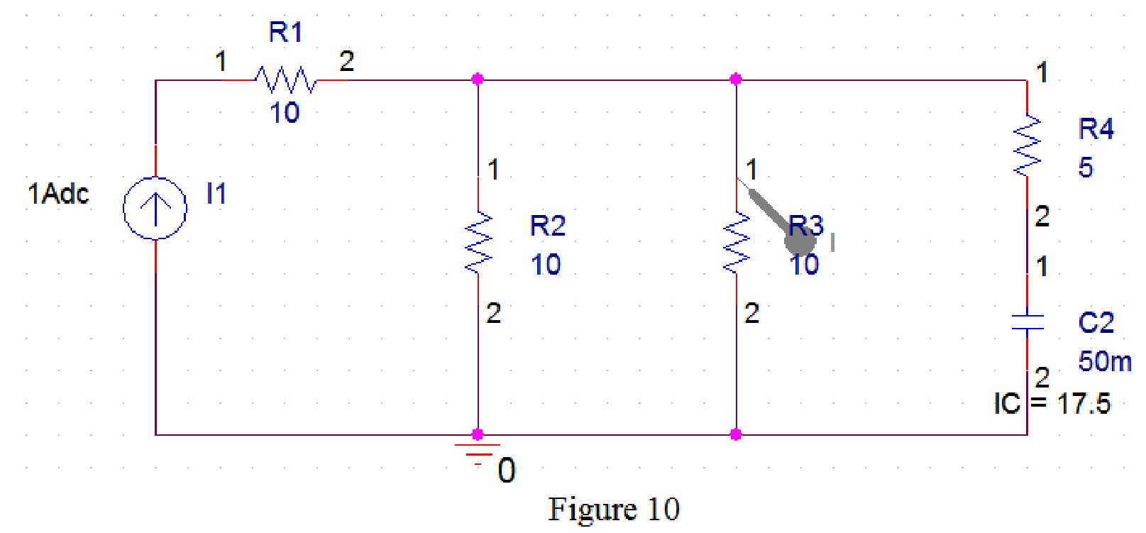
Draw the circuit diagram in PSpice as shown in Figure 10.
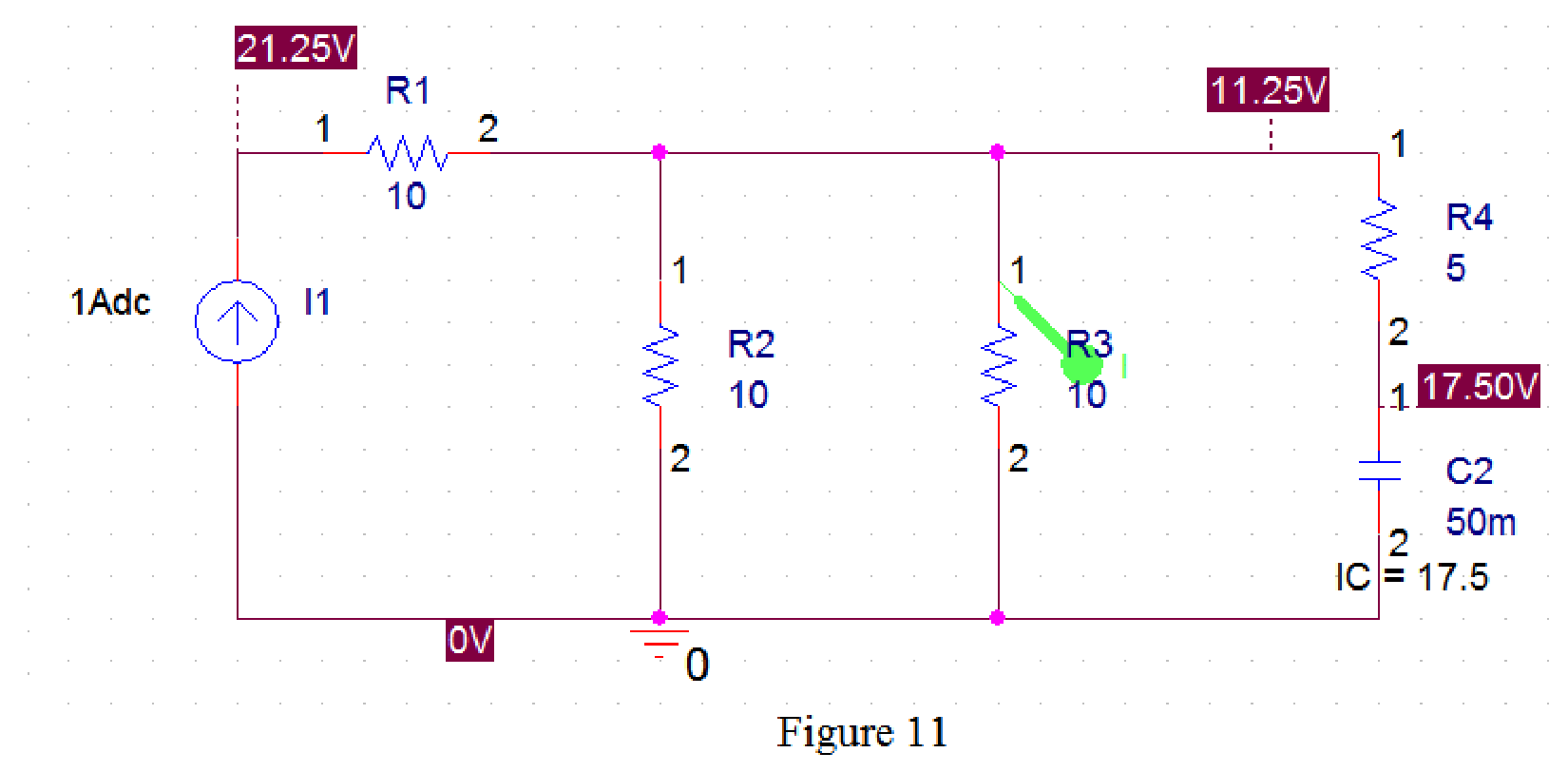
Now run the simulation and the results will be displayed as shown in Figure 11 by enabling “Enable Bias Voltage Display” icon and place the “Current Marker”
The SCHEMATIC1 dialog box is also opened with simulation result as shown in Figure 12.
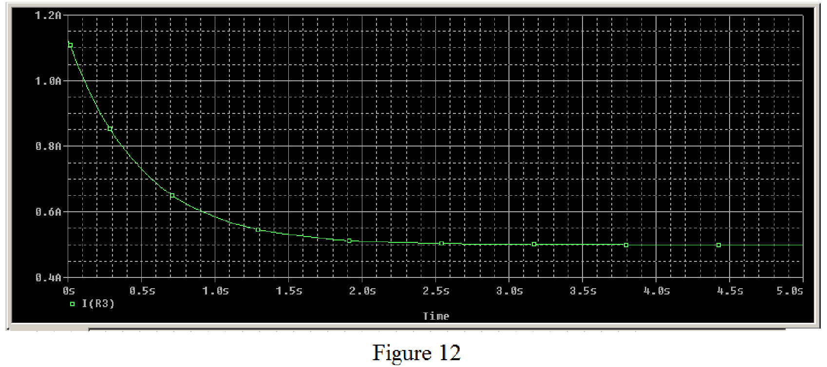
Therefore, the plot of current through the
Conclusion:
Thus, the current
Want to see more full solutions like this?
Chapter 7 Solutions
Fundamentals of Electric Circuits


- Determine ΔE if two semiconductor gages (Sg = 100) are employed in the double- potentiometer circuit shown under case 3 of Fig. 7.15. Both active gages have R1 = R2 = Rg = 500Ω. Assume Ig = 100mA, ε = +1000µ on R1 and -1000µ on R2arrow_forwardDetermine the time constant for the circuit in Fig. 7.83. 20 k2 10 kQ ww 100 pF 40 k2 30 k2arrow_forward7.56 If the input pulse in Fig. 7.124(a) is applied to the circuit in Fig. 7.124(b), determine the response f(1). 10 200 2H 100 (a) (b)arrow_forward
- Electrical Engineering Q7: Using the linear separability concept, obtain the response for OR function (rake bipolar inputs and bipolar targets). Table 7 163-164 / 489arrow_forward7:52 lecture4.pdf 1- HIGH, O-LOW EXAMPLE 3-2 ta) Develop the truth table for a 3-input AND gate (b) Determine the total number of possible input combinations for a 4-input AND gate. Solution (a) There are eight possible input combinations (2 - 8) for a 3-input AND gate. The input side of the truth table (Table 3-3) shows all eight combinations of three hits. The output side is all Os except when all three input bits are Is TABLE 3- INPUTS OUTPUT 1. (b) N-2- 16. There are 16 possible combinations of input bits for a 4-input AND gate. Related Problem Develop the truth sahle for a 4-input AND gate. |EXAMPLE 3-3 If two waveforms, A and B, are applied to the AND gate inputs as in Figure 3-11, what is the resulting output waveform? HIGH A LOW R HIGH LOW- HIGH LOW A and are both HIGH during those four time intervals Therefore X is HIGH. A FIGURE 3-11 Solution The output waveform X is HIGH only when both A and B waveforms are HIGH as shown in the timing diagram in Figure 3-11. Related Problem…arrow_forward7:44 ( Teams PBL-1 Your Friend Saad was selected to attend the Electronics workshop on “Electronic Circuits" organized by the university. In the workshop, he was exposed to many topics such as voltage divider circuits, dependent voltage source, dependent current source, independent voltage source, independent current source, application of Thevenin and Norton theorem, maximum power transfer. There were some customers’ requirements same were discussed in the workshop. Apply the concepts of the above-mentioned topics, each participant must fulfill the customer requirements. I) The input available DC voltage is 220 V and customer wants to supply the output of 30V and 50V. The available ready stock is source voltage as mentioned above and resistors values can be chosen from 1-300 KQ. Apply the concept of voltage divider with values of resistance is in k2, one value of the resistor is the last digit of your NUTECH ID and other may vary (depend on your calculations). II) Now you have two…arrow_forward
- In the circuit of Fig. 7_1, what is Leq? -Lea] m 5777. 4H a b 8H 4H 10H Fig. 7_1 2H O Leg-7 H OL-17 H OL-SH O Log-15 H OL-20 H OL-32 H 4H m m 2Harrow_forwardConsider the circuit in Fig. 7.103. Given that v(0) = 10 V, find v, and vz for t > 0. %3D 3Ω ww 10 H3 20arrow_forwardConsider the following circuit which has single input X and single output Y. This circuit represents: CLK Y Mealy Model Moore Model Both Mealy and Moore Nonearrow_forward
 Introductory Circuit Analysis (13th Edition)Electrical EngineeringISBN:9780133923605Author:Robert L. BoylestadPublisher:PEARSON
 Delmar's Standard Textbook Of ElectricityElectrical EngineeringISBN:9781337900348Author:Stephen L. HermanPublisher:Cengage Learning
 Programmable Logic ControllersElectrical EngineeringISBN:9780073373843Author:Frank D. PetruzellaPublisher:McGraw-Hill Education
 Fundamentals of Electric CircuitsElectrical EngineeringISBN:9780078028229Author:Charles K Alexander, Matthew SadikuPublisher:McGraw-Hill Education
 Electric Circuits. (11th Edition)Electrical EngineeringISBN:9780134746968Author:James W. Nilsson, Susan RiedelPublisher:PEARSON
 Engineering ElectromagneticsElectrical EngineeringISBN:9780078028151Author:Hayt, William H. (william Hart), Jr, BUCK, John A.Publisher:Mcgraw-hill Education,