
Concept explainers
Videos
Obtain the inductor current for both t < 0 and t > 0 in each of the circuits in Fig. 7.120.
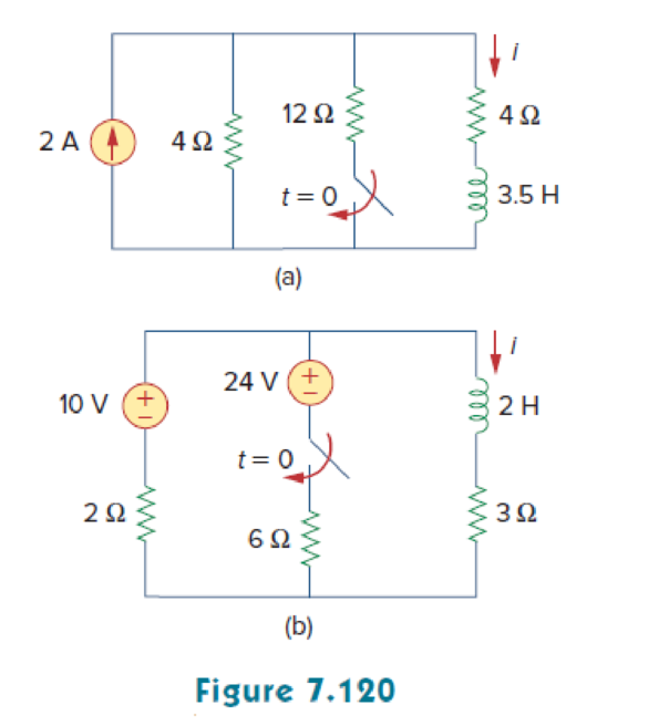
(a)
Calculate the value of inductor current
Answer to Problem 54P
The value of inductor current
Explanation of Solution
Given data:
Refer to Figure 7.120 in the textbook.
The value of inductance L in Figure 7.120(a) is
Formula used:
Write the general expression to find the complete response of current for the RL circuit.
Here,
Write the expression to calculate the time constant for the RL circuit.
Here,
L is the inductance of the inductor.
Calculation:
Figure 1 shows the modified circuit diagram when
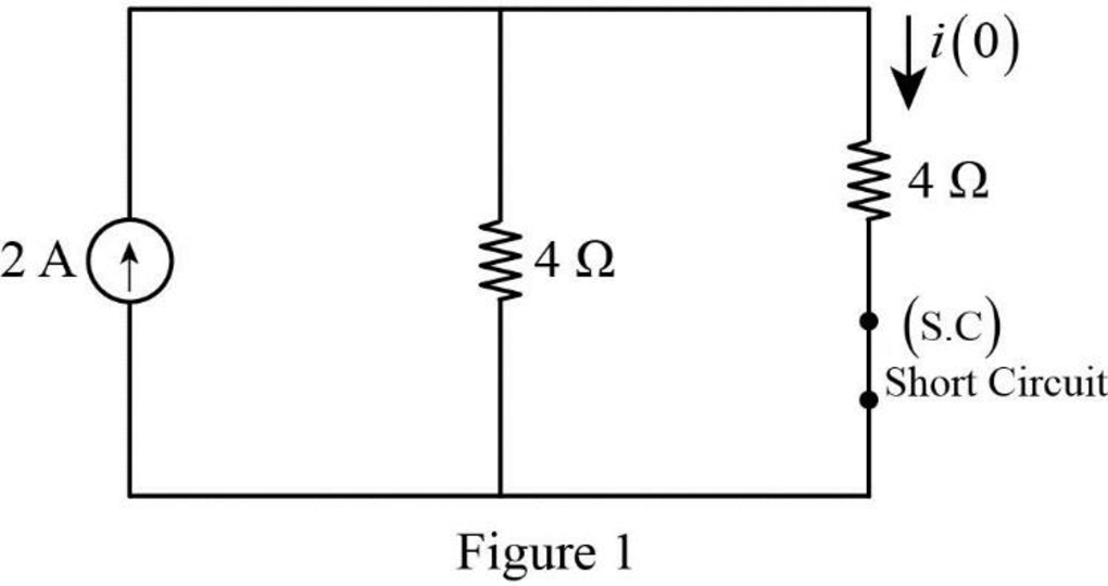
In Figure 1, the switch is kept in open position for all
Therefore, the inductor current
Figure 2 shows the modified circuit diagram when the switch is kept in close position for all
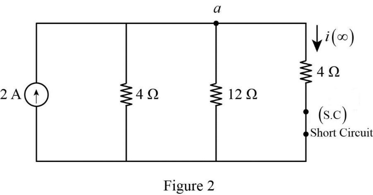
Apply Kirchhoff’s current law at node a.
Rearrange the equation as follows,
The final inductor current
Substitute
Figure 3 shows the equivalent resistance at the inductor terminal.
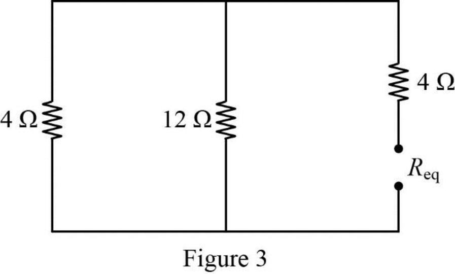
In Figure 3, the equivalent resistance is calculated as follows.
Substitute
Substitute the units
Substitute
Therefore, the inductor current
Conclusion:
Thus, the value of inductor current
(b)
Calculate the value of inductor current
Answer to Problem 54P
The value of inductor current
Explanation of Solution
Given data:
Refer to Figure 7.120 in the textbook.
The value of inductance L in Figure 7.120(b) is
Calculation:
Figure 4 shows the modified circuit diagram when switch is kept open for a long time at
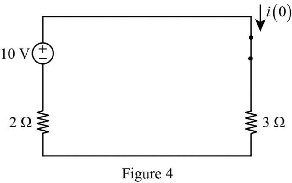
In Figure 4,
Rearrange the equation as follows,
Therefore, the inductor current
Figure 5 shows the redrawn circuit when switch is kept in closed position at
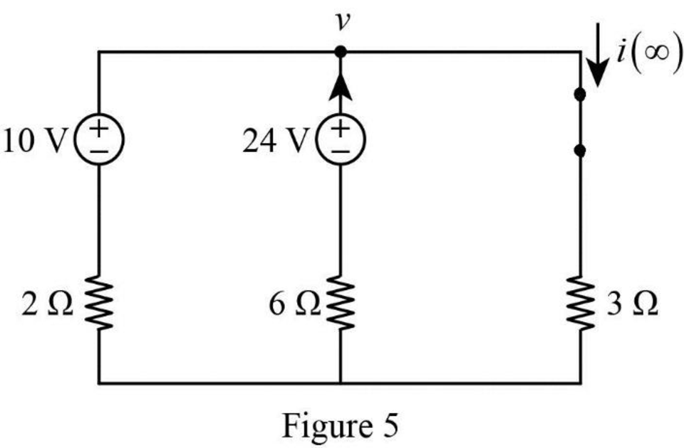
In Figure 5, apply Kirchhoff’s current law at node v.
Rearrange the equation as follows,
The final inductor current
Substitute
Figure 6 shows the equivalent resistance at the inductor terminal.
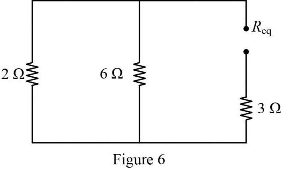
In Figure 6, the equivalent resistance is calculated as follows.
Substitute
Substitute the units
Substitute
Therefore, the inductor current
Conclusion:
Thus, the value of inductor current
Want to see more full solutions like this?
Chapter 7 Solutions
Fundamentals of Electric Circuits


- Qi Find Fcwl for the fullowing fuaction using differentiation property 7. 12arrow_forward7.7μF capacitor is charged by a 125V battery and then is disconnected from the battery. When this capacitor (C1) is then connected to a second (initially uncharged) capacitor, C2, the final voltage on each capacitor is 15V. What is the value of C2? [Hint: Charge is conserved.]arrow_forwardThe switch in Fig. has been in position A to B. The switch is a make-before-break type so that there is no interruption n the inductor current. (a) i(t) for > 0, (b) v just after te switch has been moved to position B, (c) v(t) long after the switch is in position B.arrow_forward
- An independent voltage source is characterized by a terminal current which is completely independent of the voltage across it. Select one: True Falsearrow_forward7.56 If the input pulse in Fig. 7.124(a) is applied to the circuit in Fig. 7.124(b), determine the response f(1). 10 200 2H 100 (a) (b)arrow_forward7:44 ( Teams PBL-1 Your Friend Saad was selected to attend the Electronics workshop on “Electronic Circuits" organized by the university. In the workshop, he was exposed to many topics such as voltage divider circuits, dependent voltage source, dependent current source, independent voltage source, independent current source, application of Thevenin and Norton theorem, maximum power transfer. There were some customers’ requirements same were discussed in the workshop. Apply the concepts of the above-mentioned topics, each participant must fulfill the customer requirements. I) The input available DC voltage is 220 V and customer wants to supply the output of 30V and 50V. The available ready stock is source voltage as mentioned above and resistors values can be chosen from 1-300 KQ. Apply the concept of voltage divider with values of resistance is in k2, one value of the resistor is the last digit of your NUTECH ID and other may vary (depend on your calculations). II) Now you have two…arrow_forward
- Find the time constant for each of the circuits in Fig. 7.95. 48 Ω 160 2 40 Ω 20 mAns: wwarrow_forwardIn the circuit of Fig. 7_1, what is Leq? -Lea] m 5777. 4H a b 8H 4H 10H Fig. 7_1 2H O Leg-7 H OL-17 H OL-SH O Log-15 H OL-20 H OL-32 H 4H m m 2Harrow_forward1. 7.11 There is no energy stored in the capacitor at the time the switch inthe circuit makes contact with terminal a. The switch remains at positiona for 32 ms and then moves instantaneously to position b. How manymilliseconds after making contact with terminal a does the op ampsaturate?arrow_forward
- Electrical Engineering Q7: Using the linear separability concept, obtain the response for OR function (rake bipolar inputs and bipolar targets). Table 7 163-164 / 489arrow_forwardConsider the circuit in Fig. 7.103. Given that v(0) = 10 V, find v, and vz for t > 0. %3D 3Ω ww 10 H3 20arrow_forwardWhich of the following statements are true for an inductor? Select all the correct answers. a) The current through it is proportional to the derivative of the voltage across it: i is proportional to dv/dt b) The voltage across it is proportional to the derivative of the current through it. v is proportional to di/dt c) It can be replaced with a short circuit when finding the DC response d) It can be replaced with an open circuit when finding the DC response e) When combined in series, they combine like resistors in series f) When combined in series, they combine the same as resistors in parallel g) When combined in parallel, they combine like resistors in series h) When combined in parallel, they combine like resistors in parallel i) The voltage across it can not change instantly j) The current through it can not change instantlyarrow_forward
 Introductory Circuit Analysis (13th Edition)Electrical EngineeringISBN:9780133923605Author:Robert L. BoylestadPublisher:PEARSON
 Delmar's Standard Textbook Of ElectricityElectrical EngineeringISBN:9781337900348Author:Stephen L. HermanPublisher:Cengage Learning
 Programmable Logic ControllersElectrical EngineeringISBN:9780073373843Author:Frank D. PetruzellaPublisher:McGraw-Hill Education
 Fundamentals of Electric CircuitsElectrical EngineeringISBN:9780078028229Author:Charles K Alexander, Matthew SadikuPublisher:McGraw-Hill Education
 Electric Circuits. (11th Edition)Electrical EngineeringISBN:9780134746968Author:James W. Nilsson, Susan RiedelPublisher:PEARSON
 Engineering ElectromagneticsElectrical EngineeringISBN:9780078028151Author:Hayt, William H. (william Hart), Jr, BUCK, John A.Publisher:Mcgraw-hill Education,