
Concept explainers
Videos
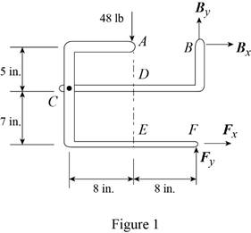
The 48-lb load can be moved along the line of action shown and applied at A, D, or E. Determine the components of the reactions at B and F if the 48-lb load is applied (a) at A, (b) at D, (c) at E.
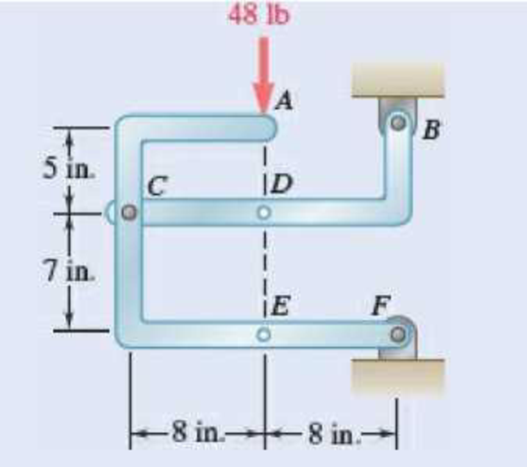
Fig. P6.88 and P6.89
SOLUTION
Free body: Entire frame:
The following analysis is valid for (a), (b) and (c) since the position of the load along its line of action is immaterial.
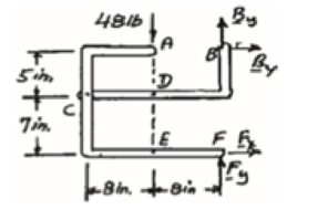
 ∑MF = 0: (48 lb)(8 in.) − Bx (12 in.) = 0
Bx = 32 lb Bx = 32 lb →
 ∑Fx = 0: 32 lb + Fx = 0
Fx = −32 lb Fx = 32 lb ←
+↑ ∑Fy = 0: By + Fy − 48 lb = 0 (1)
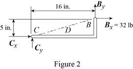
a) Load applied at A.
Free body: Member CDB
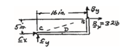
CDB is a two-force member. Thus, the reaction at B must be directed along BC.
From Eq. (1): 10 lb + Fy − 48 lb = 0
Fy = 38 lb Fy = 38 lb ↑
Thus reactions are:
Bx = 32.0 lb →, By = 10.00 lb ↑
Fx = 32.0 lb ←, Fy = 38.00 lb ↑
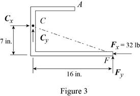
(b) Load applied at D.
Free body: Member ACF.
ACF is a two-force member. Thus, the reaction at F must be directed along CF.
From Eq. (1): By + 14 lb – 48 lb = 0
By = 34 lb, By = 34 lb ↑
Thus, reactions are:
Bx = 32.0 lb ←, By = 34.00 lb ↑
Fx = 32.0 lb →, Fy = 14.00 lb ↑
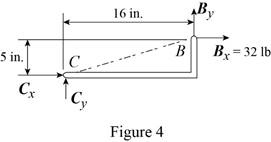
(c) Load applied at E.
Free body: Member CDB.
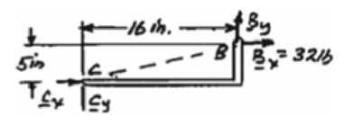
This is the same free body as in Part (a).
Reactions are same as (a)
(a)
The components of reaction at
Answer to Problem 6.88P
The components of reaction at
Explanation of Solution
The arrangement is shown in Fig. P6.88. The free-body diagram of the entire frame is given in Figure 1.
Write the expressions for equilibrium for the given system using the conditions on moments
The counter clockwise moments at
The sum of
The sum of
The load is applied at
Conclusion:
Apply the condition in equation (I) to the free-body diagram in Figure 1 and solve for
Apply the condition in equation (II) to the free-body diagram in Figure 1 and solve for
Apply the condition in equation (III) to the free-body diagram in Figure 1.
From the free-body diagram in Figure 2, write the expression connecting the components of the reaction
Substitute
Substitute
Therefore, the components of reaction at
(b)
The components of reaction at
Answer to Problem 6.88P
The components of reaction at
Explanation of Solution
The
The load is applied at
Conclusion:
From the free-body diagram in Figure 3, write the expression connecting the components of the reaction
Substitute
Substitute
Therefore, the components of reaction at
(c)
The components of reaction at
Answer to Problem 6.88P
The components of reaction at
Explanation of Solution
The
The load is applied at
Conclusion:
The free-body diagram of the member
Therefore, the components of reaction at
Want to see more full solutions like this?
Chapter 6 Solutions
Vector Mechanics for Engineers: Statics


- A slender bar of length L = 400 mm is held in equilibrium, with one end touching a frictionless wall and the other end attached to a wire of length S = 600 mm as illustrated. Knowing that the weight of the bar is 147 N (which acts at the mid-length of the bar), determine: a. the distance h. b. the tension in the wire. c. the reaction at B. C. Вarrow_forward4. Determine the reaction at C, if a horizontal circular platform of radius "R" is supported at three points A, B, C on its circumference. A and B are 90° apart and C is 120° from A. The platform carries a vertical load of 400 kN at its center and one of 100 kN at a point D on the circumference diametrically opposite Aarrow_forwardQuestion 1 (Type B): A 100 N boom is supported by a pin at A and a cable at C. Determine the magnitudes of the components of the reaction at A and the tension in the cable CD. D 50° 12 kN/m B -3 m 1 marrow_forward
- A 20-kg ladder used to reach high shelves in a storeroom is supported by two flanged wheels A and B mounted on a rail and by a flangeless wheel C resting against a rail fixed to the wall. An 80-kg man stands on the ladder and leans to the right. The line of action of the combined weight W of the man and ladder intersects the floor at point D. Determine the reactions at A, B, and C.arrow_forwardProblem: Determine reactions at B and D of the frame shown. 500 lb A 6 ft F B D. 2 ft E 2000 lb -5 ft- -5 ft-arrow_forwardPROBLEM 6.84 Determine the components of the reactions at D and E if the frame is loaded by a clockwise couple of magnitude 150 N·m applied (a) at A, (b) at B. m -ns at A and 'C 0.4 m 0.4 m A B C -0.6 m 0.6 m - D -0.6 m Earrow_forward
- For the shown frame and loads P=972 KN and Q=1944 KN, 3 m 3 m→ B 1.5 m A 1 m 8 m 6 m magnitude of y-component of reaction at B (KN) a. 216 b. 270 c. 324 d. 337.5 е. 378 magnitude of x-component of reaction at B (KN) a. 5616 b. 2808 c. 7020 d. 8424 e. 9828 magnitude of x-component of reaction at C (KN) magnitude of y-component of reaction at C (KN) magnitude of y-component of reaction at A (KN)arrow_forwardProblem 2: (40 points) The horizontal boom is supported by the cables AB and CD and by a ball-and- socket joint at O. Determine the reactions present for equilibrium at point O when L = 15kN and x = 41 B. 2m 3 m 3 m 4 m 6 marrow_forwardThe T-shaped bracket shown is supported by a small wheel at E and pegs at C and D . Neglecting the effect of friction, determine the reactions at C, D, and E when 0= 30°.arrow_forward
- Knowing that P = 6.26 kN, find the rectangular components of the reactions in A and H, and use the method of your preference to find at least 5 bars whose force is different from 0, and indicate whether it is in compression or tension.arrow_forwardEQULIBRIUM OF RIGID BODIES - 3D The 6-m pole ABC is acted upon by a force P as shown. The pole is held by a ball-and-socket joint at A and by two cables BD and BE. If the tension in cable BE is 251 N and if a = 3m, determine the magnitude of the reaction (N) at A along the z-axis. Round off only on the final answer expressed in 3 decimal places.arrow_forwardGoogle Lens Q2/ Knowing that the forces values given as: F1=32 N , F2=45 N , F3=60 N , *1=0.7 m , x2=0.4m , H=1.5m.a) Determine the x components of reactions at fixed support point Aarrow_forward
 Elements Of ElectromagneticsMechanical EngineeringISBN:9780190698614Author:Sadiku, Matthew N. O.Publisher:Oxford University Press
 Mechanics of Materials (10th Edition)Mechanical EngineeringISBN:9780134319650Author:Russell C. HibbelerPublisher:PEARSON
 Thermodynamics: An Engineering ApproachMechanical EngineeringISBN:9781259822674Author:Yunus A. Cengel Dr., Michael A. BolesPublisher:McGraw-Hill Education
 Control Systems EngineeringMechanical EngineeringISBN:9781118170519Author:Norman S. NisePublisher:WILEY
 Mechanics of Materials (MindTap Course List)Mechanical EngineeringISBN:9781337093347Author:Barry J. Goodno, James M. GerePublisher:Cengage Learning
 Engineering Mechanics: StaticsMechanical EngineeringISBN:9781118807330Author:James L. Meriam, L. G. Kraige, J. N. BoltonPublisher:WILEY