
Concept explainers
Videos
A Pratt roof truss is loaded as shown. Determine the force members FH, FI, and GI.
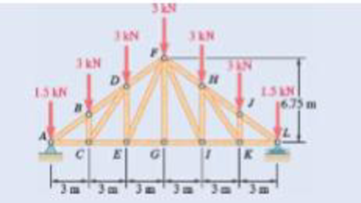
Fig. P6.55 and P6.56
The force in the members
Answer to Problem 6.56P
The force in the members
Explanation of Solution
The Pratt roof truss is loaded as shown in the figure. There is load at all the point on the top. The free body diagram of the given arrangement is given by Figure 1.
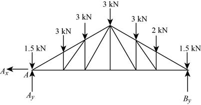
Figure 1
The total load on the truss is given from the figure as,
By symmetry the
The section’s free body diagram is given as,
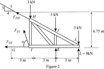
The tangent of the angle
The angle is derived from the tangent value as,
From the diagram the sum of the moments in the counter clockwise direction about
From the diagram the sum of the moments in the counter clockwise direction about
From the diagram the sum of the moments in the counter clockwise direction about
Conclusion:
Solve for
Solve for
Solve for
Therefore, the force in the members
Want to see more full solutions like this?
Chapter 6 Solutions
Vector Mechanics for Engineers: Statics


- (3) Using the method of sections, determine the force in member CG and state whether it is in tension or compression. 1.5 m, 1.5 m, 1.5 m. 1.5 m, 1.5 m, 1.5 m 2 kN 2 kN 12 kN 2 kN 1 kN 2 kN 1 kN F. H. 2 m Fig. P6.10arrow_forward6.43 Determine the force in members BD and DE of the truss shown. Answer 6.44 Determine the force in members DG and EG of the truss shown. Answer Fig. P6.43 and P6.44 2.4 m 2.4 m 2.4 m 135 KN 135 kN 135 kN A B D F 4.5 m с E Garrow_forwardDetermine the force in member DE and in each of the members located to the left of DE for the inverted Howe roof truss shown. State whether each member is in tension or compression. Fig. P6. 17arrow_forward
- 6.1 through 6.8 Using the method of joints, determine the force in each member of the truss shown. State whether each member is in tension or compression. 800 lb A B 4 ft -7.5 ft Fig. P6.1arrow_forward6.27 Determine the force in each member of the truss shown. State whether each member is in tension or compression. 15 kips B F -10 ft- 5 ft Fig. P6.27 D E 40 kips -10 ft- C Go 5 ft 4 ft ↑ 6 ft 10 ftarrow_forwardSolve Prob. 6.67 assuming that the 9-kip load has been removed.(Reference to Problem 6.67):The diagonal members in the center panels of the truss shown are very slender and can act only in tension; such members are known as counters. Determine the force in member DE and in the counters that are acting under the given loading.arrow_forward
- 6.9 and 6.10 Determine the force in each member of the truss shown. State whether each member is in tension (7) or compression (C). Answer Fig. P6.9 A 8 kN 3 m- B D 3 m- cl F E 1.6 m 1.6 marrow_forward-2 m -2 m – 4.5 kN 1.4 kN E 2.8 kN Do G 0.5 m F 1 kN I kN B 3 m I kN. I kN A |C I 1 m '1m 1 m 1 m Fig. P6.15 and P6.16 6.16 For the Gambrel roof truss shown, determine the force in members CG and CI and in each of the members located to the right of the centerline of the truss. State whether each member is in tension or compression.arrow_forward6.1 through 6.8 Using the method of joints, determine the force in each member of the truss shown, State whether each member is in tension or compression. 48 kN 3 m 4 m 1.25 m 300 Ib Ao 4 m 3.2 m 20 in. 84 kN 48 in. 3 m- 15 in. Fig. P6.1 Fig. P6.2 Fig. P6.3arrow_forward
- Solve Prob. 6.39 for P = 0 and Q = (-900 N)k.(Reference to Problem 6.39):The truss shown consists of nine members and is supported by a ball-and-socket at B , a short link at C , and two short links at D. (a) Check that this truss is a simple truss, that it is completely constrained, and that the reactions at its supports are statically determinate. (b) Determine the force in each member for P= (-1200 N)j and Q = 0.arrow_forward6.33 For the given loading, determine the zero-force members in each of the two trusses shown. A Fo D O G Fig. P6.33 B H P (a) I P E C A Do Go P C FO F (b) B P OE OH Qarrow_forward-6.80 For the frame and loading shown, determine the components of all forces acting on member ABC. B 1.2 m S0 kN 1.5 m 1.5 m- Fig. P6.80arrow_forward
 Elements Of ElectromagneticsMechanical EngineeringISBN:9780190698614Author:Sadiku, Matthew N. O.Publisher:Oxford University Press
 Mechanics of Materials (10th Edition)Mechanical EngineeringISBN:9780134319650Author:Russell C. HibbelerPublisher:PEARSON
 Thermodynamics: An Engineering ApproachMechanical EngineeringISBN:9781259822674Author:Yunus A. Cengel Dr., Michael A. BolesPublisher:McGraw-Hill Education
 Control Systems EngineeringMechanical EngineeringISBN:9781118170519Author:Norman S. NisePublisher:WILEY
 Mechanics of Materials (MindTap Course List)Mechanical EngineeringISBN:9781337093347Author:Barry J. Goodno, James M. GerePublisher:Cengage Learning
 Engineering Mechanics: StaticsMechanical EngineeringISBN:9781118807330Author:James L. Meriam, L. G. Kraige, J. N. BoltonPublisher:WILEY