
Mechanics of Materials (MindTap Course List)
9th Edition
ISBN: 9781337093347
Author: Barry J. Goodno, James M. Gere
Publisher: Cengage Learning
expand_more
expand_more
format_list_bulleted
Concept explainers
Videos
Textbook Question
thumb_up100%
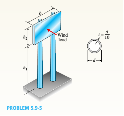
Chapter 5, Problem 5.9.5P
A sign for an automobile service station is supported by two aluminum poles of hollow circular cross section, as shown in the figure. The poles are being designed to resist a wind pressure of 75 lb/ft" against the full area of the sign. The dimensions of the poles and sign are hx= 20 ft, /r =5 ft, and h = 10 ft. To prevent buckling of the walls of the poles, the thickness e is specified as one-tenth the outside diameter d.
(a) Determine the minimum required diameter of the poles based upon an allowable bending stress of 7500 psi in the aluminum.
(b) Determine the minimum required diameter based upon an allowable shear stress of 300 psi.
Expert Solution & Answer

Trending nowThis is a popular solution!

Students have asked these similar questions
A sign for an automobile service station is supported by two aluminum poles of hollow circular cross section, as shown in the figure. The poles are being designed to resist a wind pressure of 70 lb/ft^2 against the full area of the sign. The dimensions of the poles and sign are h1 = 16 ft, h2 = 7 ft, and b = 13 ft. To prevent buckling of the walls of the poles, the thickness t is specified as one tenth the outside diameter d.
(a) Determine the minimum required diameter of the poles based upon an allowable bending stress of 7100 psi in the aluminum. Round your answer to two decimal places.
d = ___ in.
(b) Determine the minimum required diameter based upon an allowable shear stress of 2100 psi. Round your answer to two decimal places.
d = ___ in.
SEATWORK
The steel strut transmits a compressive
force P=75 kN as shown in the figure. The
strut has a hallow cross section with a
thickness of 12 mm, and the angle 0
between the strut and the horizontal and
the horizontal plane is 45°. An 18-mm
diameter pin through the strut transmits
the compressive force to two gusset plates
Pin
that are welded to the base. Four 20-mm
diameter bolts anchor the plate to
concrete. The thickness of the gusset is 16
mm. The thickness of the base plate is 16
Gusset,
Strut
Base plate
Bolts
mm.
Calculate the following.
a. The bearing stress between the pin and the gusset.
b. The shearing stress in the bolts.
The bearing stress between the anchor bolts and the base plate.
с.
Strut
Problem 7.34
Consider the two-member frame shown in (Figure 1)
Suppose that w = 2.6 kN/m, w = 1.9 kN/m Follow
the sign convention.
Figure
-1.5m
-1.5m
15m
1.5m
1 of 1
Part A
Determine the normal force at point E.
Express your answer to three significant figures and include the appropriate units.
NE- Value
Submit Previous Answers Request Answer
Incorrect; Try Again; 4 attempts remaining
Part B
Determine the shear force at point E
Express your answer to three significant figures and include the appropriate units.
VE =
Part C
HA
Value
Mg Value
Submit
Units
Heavest Answ
Determine the magnitude of the moment at point E.
Express your answer to three significant figures and include the appropriate units.
< Return to Assignment
Units
Pearson
?
Units
Provide Feedback
16
O ?
6 of 6
Revise
Chapter 5 Solutions
Mechanics of Materials (MindTap Course List)
Ch. 5 - A steel wire with a diameter of d = 1/16 in. is...Ch. 5 - A copper wire having a diameter ofd = 4 mm is bent...Ch. 5 - A 4.75-in, outside diameter polyethylene pipe...Ch. 5 - A cantilever beam AB is loaded by a couple M0at...Ch. 5 - A thin strip of steel with a length of L =19 in....Ch. 5 - A bar of rectangular cross section is loaded and...Ch. 5 - A simply supported beam with a length L = 10 ft...Ch. 5 - A cantilever beam is subjected to a concentrated...Ch. 5 - A thin strip of hard copper (E = 16,000 ksi)...Ch. 5 - A steel wire (E = 200 GPa) of a diameter d = L25...
Ch. 5 - A thin, high-strength steel rule (E = 30 x 10ft...Ch. 5 - A simply supported wood beam AB with a span length...Ch. 5 - Beam ABC has simple supports at A and B and an...Ch. 5 - A simply supported beam is subjected to a in early...Ch. 5 - Each girder of the lift bridge (sec figure) is 180...Ch. 5 - A freight-car axle AS is loaded approximately as...Ch. 5 - A seesaw weighing 3 lb/ft of length is occupied by...Ch. 5 - During construction of a highway bridge, the main...Ch. 5 - The horizontal beam ABC of an oil-well pump has...Ch. 5 - A railroad tie (or sleeper) is subjected to two...Ch. 5 - A fiberglass pipe is lifted by a sling, as shown...Ch. 5 - A small dam of height h = 2.0 m is constructed of...Ch. 5 - Determine the maximum tensile stress (7, (due to...Ch. 5 - Determine the maximum bending stress emaxdue to...Ch. 5 - A simple beam A B of a span length L = 24 ft is...Ch. 5 - Determine the maximum tensile stress erand maximum...Ch. 5 - A cantilever beam A3, loaded by a uniform load and...Ch. 5 - A canti lever beam A B of a n isosceles t...Ch. 5 - A cantilever beam, a C12 x 30 section, is...Ch. 5 - A frame ABC travels horizontally with an...Ch. 5 - A beam ABC with an overhang from B to C supports a...Ch. 5 - A cantilever beam AB with a rectangular cross...Ch. 5 - A beam with a T-section is supported and loaded as...Ch. 5 - Consider the compound beam with segments AB and...Ch. 5 - A small dam of a height h = 6 ft is constructed of...Ch. 5 - A foot bridge on a hiking trail is constructed...Ch. 5 - A steel post (E=30×106) having thickness t = 1/8...Ch. 5 - Beam ABCDE has a moment release just right of...Ch. 5 - A simply supported wood beam having a span length...Ch. 5 - A simply supported beam (L = 4.5 m) must support...Ch. 5 - The cross section of a narrow-gage railway bridge...Ch. 5 - A fiberglass bracket A BCD with a solid circular...Ch. 5 - A cantilever beanie B is loaded by a uniform load...Ch. 5 - A simple beam of length L = 5 m carries a uniform...Ch. 5 - A simple beam AB is loaded as shown in the figure....Ch. 5 - A pontoon bridge (see figure) is constructed of...Ch. 5 - A floor system in a small building consists of...Ch. 5 - The wood joists supporting a plank Floor (see...Ch. 5 - A beam ABC with an overhang from B to C is...Ch. 5 - -12 A "trapeze bar" in a hospital room provides a...Ch. 5 - A two-axle carriage that is part of an over head...Ch. 5 - A cantilever beam AB with a circular cross section...Ch. 5 - A propped cantilever beam A BC (see figure) has a...Ch. 5 - A small balcony constructed of wood is supported...Ch. 5 - A beam having a cross section in the form of an un...Ch. 5 - A beam having a cross section in the form of a...Ch. 5 - Determine the ratios of the weights of four beams...Ch. 5 - Prob. 5.6.20PCh. 5 - A steel plate (called a cover ploie) having...Ch. 5 - A steel beam ABC is simply supported at A and...Ch. 5 - A retaining wall 6 ft high is constructed of...Ch. 5 - A retaining wall (Fig. a) is constructed using...Ch. 5 - A beam of square cross section (a = length of each...Ch. 5 - The cross section of a rectangular beam having a...Ch. 5 - A tapered cantilever beam A B of length L has...Ch. 5 - .2 A ligmio.irc ii supported by two vorlical beams...Ch. 5 - Prob. 5.7.3PCh. 5 - Prob. 5.7.4PCh. 5 - Prob. 5.7.5PCh. 5 - A cantilever beam AB with rectangular cross...Ch. 5 - A simple beam ABC having rectangular cross...Ch. 5 - A cantilever beam AB having rectangular cross...Ch. 5 - The shear stresses t in a rectangular beam arc...Ch. 5 - .2 Calculate the maximum shear stress tmaxand the...Ch. 5 - A simply supported wood beam is subjected to...Ch. 5 - A simply supported wood beam with overhang is...Ch. 5 - Two wood beams, each of rectangular cross section...Ch. 5 - A cantilever beam of length L = 2 m supports a...Ch. 5 - A steel beam of length L = 16 in. and...Ch. 5 - A beam of rectangular cross section (width/) and...Ch. 5 - A laminated wood beam on simple supports (figure...Ch. 5 - A laminated plastic beam of square cross section...Ch. 5 - A wood beam AB on simple supports with span length...Ch. 5 - A simply supported wood beam of rectangular cross...Ch. 5 - A square wood platform is 8 ft × 8 ft in area and...Ch. 5 - A wood beam ABC with simple supports at A and B...Ch. 5 - A wood pole with a solid circular cross section (d...Ch. 5 - A simple log bridge in a remote area consists of...Ch. 5 - A vertical pole consisting of a circular tube of...Ch. 5 - A circular pole is subjected to linearly varying...Ch. 5 - A sign for an automobile service station is...Ch. 5 - A steel pipe is subjected to a quadratic...Ch. 5 - -1 through 5.10-6 A wide-flange beam (see figure)...Ch. 5 - -1 through 5.10-6 A wide-flange beam (see figure)...Ch. 5 - -1 through 5.10-6 A wide-flange beam (see figure)...Ch. 5 - -1 through 5.10-6 A wide-flange beam (see figure)...Ch. 5 - -1 through 5.10-6 A wide-flange beam (see figure)...Ch. 5 - -1 through 5.10-6 A wide-flange beam (see figure)...Ch. 5 - A cantilever beam AB of length L = 6.5 ft supports...Ch. 5 - A bridge girder A B on a simple span of length L =...Ch. 5 - A simple beam with an overhang supports a uniform...Ch. 5 - A hollow steel box beam has the rectangular cross...Ch. 5 - A hollow aluminum box beam has the square cross...Ch. 5 - The T-beam shown in the figure has cross-sectional...Ch. 5 - Calculate the maximum shear stress tmax. in the...Ch. 5 - A prefabricated wood I-beam serving as a floor...Ch. 5 - A welded steel gird crhaving the erass section...Ch. 5 - A welded steel girder having the cross section...Ch. 5 - A wood box beam is constructed of two 260 mm × 50...Ch. 5 - A box beam is constructed of four wood boards as...Ch. 5 - Two wood box beams (beams A and B) have the same...Ch. 5 - A hollow wood beam with plywood webs has the...Ch. 5 - A beam of a T cross section is formed by nailing...Ch. 5 - The T-beam shown in the figure is fabricated by...Ch. 5 - A steel beam is built up from a W 410 × 85 wide...Ch. 5 - The three beams shown have approximately the same...Ch. 5 - Two W 310 × 74 Steel wide-flange beams are bolted...Ch. 5 - A pole is fixed at the base and is subjected to a...Ch. 5 - A solid circular pole is subjected to linearly...Ch. 5 - While drilling a hole with a brace and bit, you...Ch. 5 - An aluminum pole for a street light weighs 4600 N...Ch. 5 - A curved bar ABC having a circular axis (radius r...Ch. 5 - A rigid Trame ABC is formed by welding two steel...Ch. 5 - A palm tree weighing 1000 lb is inclined at an...Ch. 5 - A vertical pole of aluminum is fixed at the base...Ch. 5 - Because of foundation settlement, a circular tower...Ch. 5 - A steel bracket of solid circular cross section is...Ch. 5 - A cylindrical brick chimney of height H weighs w =...Ch. 5 - A flying but tress transmit s a load P = 25 kN,...Ch. 5 - A plain concrete wall (i.e., a wall with no steel...Ch. 5 - A circular post, a rectangular post, and a post of...Ch. 5 - Two cables, each carrying a tensile force P = 1200...Ch. 5 - Prob. 5.12.16PCh. 5 - A short column constructed of a W 12 × 35...Ch. 5 - A short column with a wide-flange shape is...Ch. 5 - A tension member constructed of an L inch angle...Ch. 5 - A short length of a C 200 × 17.1 channel is...Ch. 5 - The beams shown in the figure are subjected to...Ch. 5 - The beams shown in the figure are subjected to...Ch. 5 - A rectangular beam with semicircular notches, as...Ch. 5 - A rectangular beam with semicircular notches, as...Ch. 5 - A rectangular beam with notches and a hole (see...
Knowledge Booster


Learn more about
Need a deep-dive on the concept behind this application? Look no further. Learn more about this topic, mechanical-engineering and related others by exploring similar questions and additional content below.Similar questions
- A large precast concrete panel for a warehouse is raised using two sets of cables at two lift lines, as shown in the figure part a. Cable 1 has a length L1 = 22 Ft, cable 2 has a length L2= 10 ft, and the distance along the panel between lift points Band D is d = 14 ft (see figure part b). The total weight of the panel is W = 85 kips. Assuming the cable lift Forces F at each lift line are about equal, use the simplified model of one half of the panel in figure part b to perform your analysis for the lift position shown. Find the required cross-sectional area AC of the cable if its breaking stress is 91 ksi and a factor of safety of 4 with respect to failure is desired.arrow_forwardA cylindrical brick chimney of height H weighs w = 825 lb/ft of height (see figure). The inner and outer diameters are d1= 3 ft and d2= 4 ft, respectively. The wind pressure against the side of the chimney is p = 10 lb/ft2 of projected area. Determine the maximum height H if there is to be no tension in the brickwork.arrow_forwardA long re Lai nine: wall is braced by wood shores set at an angle of 30° and supported by concrete thrust blocks, as shown in the first part of the figure. The shores are evenly spaced at 3 m apart. For analysis purposes, the wall and shores are idealized as shown in the second part of the figure. Note that the base of the wall and both ends of the shores are assumed to be pinned. The pressure of the soil against the wall is assumed to be triangularly distributed, and the resultant force acting on a 3-meter length of the walls is F = 190 kN. If each shore has a 150 mm X 150 mm square cross section, what is the compressive stressarrow_forward
- A steel riser pipe hangs from a drill rig located offshore in deep water (see figure). (a) What is the greatest length (meters) it can have without breaking if the pipe is suspended in the air and the ultimate strength (or breaking strength) is 550 MPa? (b) If the same riser pipe hangs from a drill rig at sea, what is the greatest length? (Obtain the weight densities of steel and sea water from Table M, Appendix I. Neglect the effect of buoyant foam casings on the pipe.)arrow_forwardA sign is supported by a pipe (see figure) having an outer diameter 110 mm and inner diameter 90 mm. The dimensions of the sign are 2.0 m X 1.0 m, and its lower edge is 3.0 m above the base. Note that the center of gravity of the sign is 1.05 m from the axis of the pipe. The wind pressure against the sign is 1.5 kPa. Determine the maximum in-plane shear stresses due to the wind pressure on the sign at points /I, B, and C, located on the outer surface at the base of the pipe.arrow_forwardPROBLEM 2 The aluminum bar with cross-sectional area of 160 mm2 carries the axial loads at the position shown in the figure. Given that E=70-Gpa, compute the total change in length of the bar. 35kN 15KN 30kN 10kN 0.8 m 1.0 m 0.6 marrow_forward
- A polyethylene bar having rectangular cross section with a width 6.36 in. and depth 6 in. is centered inside a hollow steel square section with side dimension of 7 in. The polyethylene bar is then compressed by an axial force P. 0.3 in. 6 in. 7 in. 6.36 in. 7 in. At what value of the force P will the gap between the polyethylene bar and the steel tube be closed for the first time in one dimension? For polyethylene, assume E = 200 ksi and v = 0.4. Assume that the material behaves linearly elastically. (Enter the magnitude in kips.) kips What is the remaining gap between the polyethylene bar and the steel tube in the other dimension? (Enter the distance in inches between the side of the polyethylene bar and the closest side of the steel section.) in.arrow_forward1. An underwater vehicle that can be approximated as a sphere of radius r = 0.8 m is to operate at depth h=1000 m. It is constructed by joining two hemispheres with 40 equally spaced bolts, Figure Q1. The allowable stress for the bolts is 100 MPa. The sphere is filled with air at pressure p = 600 kPa. If the material of the sphere is steel with yield stress gx=600 MPa, and the factor of safety is n = 2.5 with respect to yielding, calculate the bolt diameter d and the required thickness of the sphere t. Assumptions: (a) The sphere may be treated as a thin-walled pressure vessel. (b) The sea water density p= 1000 kg/m³. (c) Buckling of the vessel will not occur. Spherical Vessel Bolts used to fix two hemispheres to each other 0.8 m Figure Q1arrow_forwardA sign is supported by a pole of hollow circular cross section, as shown in the figure. The outer and inner diameters of the pole are 10.5 in. and 8.5 in,, respectively. The pole is 42 ft high and weighs 4 kips, The sign has dimensions 8 ft x 3 ft and weighs 500 lb, Note that its center of gravity is 53.25 in. from the axis of the pole. The wind pressure against the sign is 35 lb/ft -,(a) Determine the stresses acting on a stress element at point A, which is on the outer surface of the pole at the "front" of the pole, that is, the part of the pole nearest to the viewer,(b) Determine the maximum tensile, compressive, and shear stresses at point Aarrow_forward
- A train is parked on a steel bridge as shown in the figure below. The steel bridge is simply supported by a pin support at point A and a roller support at point B. The bridge has a modulus of E0=200 GPa, 2nd moment of area Iz=1.5 m^4 and length L=200m. The train has a weight of W=2000000N and the same length as the bridge. Use the SI Unit for calculation. a) Determine the intensity of the uniformly distributed load: f= b) Write the mathematical expression for the two quantities below, in terms of parameters ?, ??, ?0, ? and ?. Determine the elastic curve formula for the deflection of the bridge. v= determine the slope formula for the bridge under the applied loading dv/dx=arrow_forwardThe structure in the sketch below consists of the two members ABC and CDE which are pin- connected at point C. The complete structure is supported by a weightless link at B and a fixed support at E. The link is perpendicular to part BCDE and pin-connected to the support at the bottom. The distributed loading acts perpendicular to the inclined part AB. The figure is not to scale. 600 N/ m A 900N 0.5m E C -1.3т- * 1m - 1m 1.2m Calculate the support reactions that develop on the frame at points B and E. Interpret your final answers on a separate complete free-body diagram of the structure ABCDE. B,arrow_forward3. An L-shaped bracket lying in a horizontal plane supports a load F = 1kN. The bracket has a hollow rectangular cross section with thickness t = 5mm and outer dimensions b = 50mm and h = 75mm. The centreline lengths of the arms are l1 = 0.5m and l2 = 0.75m.Calculate the stresses developed on the cross-section at attachment A of the L-shaped bracket.Assume : E = 2.1 x 10⁵ MPaarrow_forward
arrow_back_ios
SEE MORE QUESTIONS
arrow_forward_ios
Recommended textbooks for you
 Mechanics of Materials (MindTap Course List)Mechanical EngineeringISBN:9781337093347Author:Barry J. Goodno, James M. GerePublisher:Cengage Learning
Mechanics of Materials (MindTap Course List)
Mechanical Engineering
ISBN:9781337093347
Author:Barry J. Goodno, James M. Gere
Publisher:Cengage Learning
Everything About COMBINED LOADING in 10 Minutes! Mechanics of Materials; Author: Less Boring Lectures;https://www.youtube.com/watch?v=N-PlI900hSg;License: Standard youtube license