
Mechanics of Materials (MindTap Course List)
9th Edition
ISBN: 9781337093347
Author: Barry J. Goodno, James M. Gere
Publisher: Cengage Learning
expand_more
expand_more
format_list_bulleted
Videos
Textbook Question
Chapter 5, Problem 5.12.11P
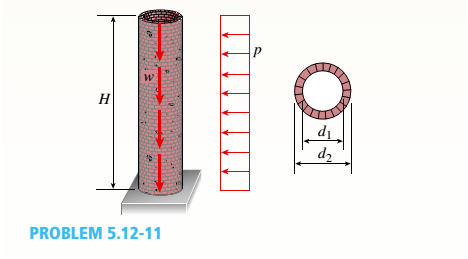
A cylindrical brick chimney of height H weighs w = 825 lb/ft of height (see figure). The inner and outer diameters are d1= 3 ft and d2= 4 ft, respectively. The wind pressure against the side of the chimney is p = 10 lb/ft2 of projected area.
Determine the maximum height H if there is to be no tension in the brickwork.
Expert Solution & Answer

Trending nowThis is a popular solution!

Students have asked these similar questions
A triangular dam is shown in the figure, base is 6-m and height is 8-m. Compute for the
factor of safety against sliding and overturning. Unit weight of concrete is 23.54 kN/cu.m.
Consider 1 meter length strip. Disregard hydrostatic uplift pressure. The coefficient
between the dam and the foundation is 0.8.
h
EXAMPLE:
7.
Show the V-M diagram using Area
Method of the following beam:
1000 lb
400 lb/ft
5 ft
R₂
10 ft
2000 lb
+
200 lb/ft
10 ft
The layer at the center of gravity of the
beam as shown in the below figure, will be
M
M
MJ
O In tension
O In compression
ONeither in tension nor in compression
Chapter 5 Solutions
Mechanics of Materials (MindTap Course List)
Ch. 5 - A steel wire with a diameter of d = 1/16 in. is...Ch. 5 - A copper wire having a diameter ofd = 4 mm is bent...Ch. 5 - A 4.75-in, outside diameter polyethylene pipe...Ch. 5 - A cantilever beam AB is loaded by a couple M0at...Ch. 5 - A thin strip of steel with a length of L =19 in....Ch. 5 - A bar of rectangular cross section is loaded and...Ch. 5 - A simply supported beam with a length L = 10 ft...Ch. 5 - A cantilever beam is subjected to a concentrated...Ch. 5 - A thin strip of hard copper (E = 16,000 ksi)...Ch. 5 - A steel wire (E = 200 GPa) of a diameter d = L25...
Ch. 5 - A thin, high-strength steel rule (E = 30 x 10ft...Ch. 5 - A simply supported wood beam AB with a span length...Ch. 5 - Beam ABC has simple supports at A and B and an...Ch. 5 - A simply supported beam is subjected to a in early...Ch. 5 - Each girder of the lift bridge (sec figure) is 180...Ch. 5 - A freight-car axle AS is loaded approximately as...Ch. 5 - A seesaw weighing 3 lb/ft of length is occupied by...Ch. 5 - During construction of a highway bridge, the main...Ch. 5 - The horizontal beam ABC of an oil-well pump has...Ch. 5 - A railroad tie (or sleeper) is subjected to two...Ch. 5 - A fiberglass pipe is lifted by a sling, as shown...Ch. 5 - A small dam of height h = 2.0 m is constructed of...Ch. 5 - Determine the maximum tensile stress (7, (due to...Ch. 5 - Determine the maximum bending stress emaxdue to...Ch. 5 - A simple beam A B of a span length L = 24 ft is...Ch. 5 - Determine the maximum tensile stress erand maximum...Ch. 5 - A cantilever beam A3, loaded by a uniform load and...Ch. 5 - A canti lever beam A B of a n isosceles t...Ch. 5 - A cantilever beam, a C12 x 30 section, is...Ch. 5 - A frame ABC travels horizontally with an...Ch. 5 - A beam ABC with an overhang from B to C supports a...Ch. 5 - A cantilever beam AB with a rectangular cross...Ch. 5 - A beam with a T-section is supported and loaded as...Ch. 5 - Consider the compound beam with segments AB and...Ch. 5 - A small dam of a height h = 6 ft is constructed of...Ch. 5 - A foot bridge on a hiking trail is constructed...Ch. 5 - A steel post (E=30×106) having thickness t = 1/8...Ch. 5 - Beam ABCDE has a moment release just right of...Ch. 5 - A simply supported wood beam having a span length...Ch. 5 - A simply supported beam (L = 4.5 m) must support...Ch. 5 - The cross section of a narrow-gage railway bridge...Ch. 5 - A fiberglass bracket A BCD with a solid circular...Ch. 5 - A cantilever beanie B is loaded by a uniform load...Ch. 5 - A simple beam of length L = 5 m carries a uniform...Ch. 5 - A simple beam AB is loaded as shown in the figure....Ch. 5 - A pontoon bridge (see figure) is constructed of...Ch. 5 - A floor system in a small building consists of...Ch. 5 - The wood joists supporting a plank Floor (see...Ch. 5 - A beam ABC with an overhang from B to C is...Ch. 5 - -12 A "trapeze bar" in a hospital room provides a...Ch. 5 - A two-axle carriage that is part of an over head...Ch. 5 - A cantilever beam AB with a circular cross section...Ch. 5 - A propped cantilever beam A BC (see figure) has a...Ch. 5 - A small balcony constructed of wood is supported...Ch. 5 - A beam having a cross section in the form of an un...Ch. 5 - A beam having a cross section in the form of a...Ch. 5 - Determine the ratios of the weights of four beams...Ch. 5 - Prob. 5.6.20PCh. 5 - A steel plate (called a cover ploie) having...Ch. 5 - A steel beam ABC is simply supported at A and...Ch. 5 - A retaining wall 6 ft high is constructed of...Ch. 5 - A retaining wall (Fig. a) is constructed using...Ch. 5 - A beam of square cross section (a = length of each...Ch. 5 - The cross section of a rectangular beam having a...Ch. 5 - A tapered cantilever beam A B of length L has...Ch. 5 - .2 A ligmio.irc ii supported by two vorlical beams...Ch. 5 - Prob. 5.7.3PCh. 5 - Prob. 5.7.4PCh. 5 - Prob. 5.7.5PCh. 5 - A cantilever beam AB with rectangular cross...Ch. 5 - A simple beam ABC having rectangular cross...Ch. 5 - A cantilever beam AB having rectangular cross...Ch. 5 - The shear stresses t in a rectangular beam arc...Ch. 5 - .2 Calculate the maximum shear stress tmaxand the...Ch. 5 - A simply supported wood beam is subjected to...Ch. 5 - A simply supported wood beam with overhang is...Ch. 5 - Two wood beams, each of rectangular cross section...Ch. 5 - A cantilever beam of length L = 2 m supports a...Ch. 5 - A steel beam of length L = 16 in. and...Ch. 5 - A beam of rectangular cross section (width/) and...Ch. 5 - A laminated wood beam on simple supports (figure...Ch. 5 - A laminated plastic beam of square cross section...Ch. 5 - A wood beam AB on simple supports with span length...Ch. 5 - A simply supported wood beam of rectangular cross...Ch. 5 - A square wood platform is 8 ft × 8 ft in area and...Ch. 5 - A wood beam ABC with simple supports at A and B...Ch. 5 - A wood pole with a solid circular cross section (d...Ch. 5 - A simple log bridge in a remote area consists of...Ch. 5 - A vertical pole consisting of a circular tube of...Ch. 5 - A circular pole is subjected to linearly varying...Ch. 5 - A sign for an automobile service station is...Ch. 5 - A steel pipe is subjected to a quadratic...Ch. 5 - -1 through 5.10-6 A wide-flange beam (see figure)...Ch. 5 - -1 through 5.10-6 A wide-flange beam (see figure)...Ch. 5 - -1 through 5.10-6 A wide-flange beam (see figure)...Ch. 5 - -1 through 5.10-6 A wide-flange beam (see figure)...Ch. 5 - -1 through 5.10-6 A wide-flange beam (see figure)...Ch. 5 - -1 through 5.10-6 A wide-flange beam (see figure)...Ch. 5 - A cantilever beam AB of length L = 6.5 ft supports...Ch. 5 - A bridge girder A B on a simple span of length L =...Ch. 5 - A simple beam with an overhang supports a uniform...Ch. 5 - A hollow steel box beam has the rectangular cross...Ch. 5 - A hollow aluminum box beam has the square cross...Ch. 5 - The T-beam shown in the figure has cross-sectional...Ch. 5 - Calculate the maximum shear stress tmax. in the...Ch. 5 - A prefabricated wood I-beam serving as a floor...Ch. 5 - A welded steel gird crhaving the erass section...Ch. 5 - A welded steel girder having the cross section...Ch. 5 - A wood box beam is constructed of two 260 mm × 50...Ch. 5 - A box beam is constructed of four wood boards as...Ch. 5 - Two wood box beams (beams A and B) have the same...Ch. 5 - A hollow wood beam with plywood webs has the...Ch. 5 - A beam of a T cross section is formed by nailing...Ch. 5 - The T-beam shown in the figure is fabricated by...Ch. 5 - A steel beam is built up from a W 410 × 85 wide...Ch. 5 - The three beams shown have approximately the same...Ch. 5 - Two W 310 × 74 Steel wide-flange beams are bolted...Ch. 5 - A pole is fixed at the base and is subjected to a...Ch. 5 - A solid circular pole is subjected to linearly...Ch. 5 - While drilling a hole with a brace and bit, you...Ch. 5 - An aluminum pole for a street light weighs 4600 N...Ch. 5 - A curved bar ABC having a circular axis (radius r...Ch. 5 - A rigid Trame ABC is formed by welding two steel...Ch. 5 - A palm tree weighing 1000 lb is inclined at an...Ch. 5 - A vertical pole of aluminum is fixed at the base...Ch. 5 - Because of foundation settlement, a circular tower...Ch. 5 - A steel bracket of solid circular cross section is...Ch. 5 - A cylindrical brick chimney of height H weighs w =...Ch. 5 - A flying but tress transmit s a load P = 25 kN,...Ch. 5 - A plain concrete wall (i.e., a wall with no steel...Ch. 5 - A circular post, a rectangular post, and a post of...Ch. 5 - Two cables, each carrying a tensile force P = 1200...Ch. 5 - Prob. 5.12.16PCh. 5 - A short column constructed of a W 12 × 35...Ch. 5 - A short column with a wide-flange shape is...Ch. 5 - A tension member constructed of an L inch angle...Ch. 5 - A short length of a C 200 × 17.1 channel is...Ch. 5 - The beams shown in the figure are subjected to...Ch. 5 - The beams shown in the figure are subjected to...Ch. 5 - A rectangular beam with semicircular notches, as...Ch. 5 - A rectangular beam with semicircular notches, as...Ch. 5 - A rectangular beam with notches and a hole (see...
Knowledge Booster


Learn more about
Need a deep-dive on the concept behind this application? Look no further. Learn more about this topic, mechanical-engineering and related others by exploring similar questions and additional content below.Similar questions
- A sign for a pizza restaurant hangs from a 2.60-m long rod extended out from a building. A cable, attached to the building, is attached to the rod at a point that is 2.10 m from the hidge. (See the figure.) The mass of the rod is 3.20 kg. The mass of the sign is 7.10 kg. The angle between the building and the rod is 69.0 degrees. The angle between the cable and the horizontal is 36.0 degrees. The tension in the cable is 117.5 N. What is the vertical component of the reaction force from then hinge on the rod?arrow_forwardAn aluminum pole for a street light weighs4600 N and supports an arm that weighs 660 N (seefigure). The center of gravity of the arm is 1.2 m from theaxis of the pole. A wind force of 300 N also acts in the (-y)direction at 9 m above the base. The outside diameter ofthe pole (at its base) is 225 mm, and its thickness is 18 mm. Determine the maximum tensile and compressivestresses σt and σc, respectively, in the pole (at its base)due to the weights and the wind force.arrow_forwardA sign for a pizza restaurant hangs from a 2.60-m long rod extended out from a building. A cable, attached to the building, is attached to the rod at a point that is 2.10 m from the hidge. (See the figure.)The mass of the rod is 5.90 kg. The mass of the sign is 9.40 kg. The angle between the building and the rod is 74.0 degrees. The angle between the cable and the horizontal is 31.0 degrees.What is the torque on the rod due to the weight of the rod alone? [Take the axis to be at the hinge.]arrow_forward
- Consider a floor crane operated by a driver which carries a drum as shown in figure. The total weight of floor crane and driver is 2700 kg acting at the point of center of gravity, G. mm; = 1 = Considering L1 = 14m, L2= 3 m L3 - 6 m, 14 = 2 m LS = 1 m; L6=7m 1. If the weight of the drum lifted by the floor crane is 800 kg, determine the total normal reaction on the rear wheels at A and total normal reaction on the front wheels at B when the boom is inclined at an angle of 25" with the horizontal, 2. Utilizing the same data given above for the same position of boom, determine the largest weight of the drum that can be lifted without causing the crane to overturn. (Hint: When the floor crane tends to overturn about point B, the wheel at A will leave the ground). Note: 1. Consider the entire system as coplanar 2. Take g 9.81 m/s wherever necessary = 9 Total normal reaction on the rear wheels at A= Total normal reaction on the front wheels at B= Largest weight of the drum=arrow_forwardThe Straw Hat crew on their journey to Laugh Tale Island found a big treasure box (W). Luffy wanted to place the treasure box (W) as shown in the figure. A 100-mm x 300 mm rectangular beam is supported in a horizontal position. At point "A", it is being held by a pin and at "B" by a cable BD inclined 3 vertical to 4 horizontal. Assume all forces are applied to the beam along its central axis. Given that Fcparallel to grain = 10.50 MPa, W = 79 kN and E = 13800 MPa. Neglecting the weight of the beam and cable, determine whether the design is safe. Cable 2.4 m 2.4 marrow_forwardFind the internal forces N, V, M at point C and D of the three-hinged parabolic arch shown. 22 kip/ft 10 kip 20 ft 10 ft 12 ft B V А 30 ft 30 ft ->arrow_forward
- The prismatic bar AC is supported by a hinge at C and cable ADB that runs through a frictionless pulley at D as shown in the figure. What is the tension in the cable if the bar weighs 5 Ib/ft? 3 ft 5 ft в 5 ftarrow_forward3. A board whose width changes as w(x) = 2(√I-√√) (0 ≤ x ≤ L), as shown is fixed on the left edge. Here L is the length of the board. The material has an area mass density (per unit area) of pkg/m² dA w(x) = 2(√L-√x) L F(x,y) a) What is the weight of the board? Derive it by integrating weight of a differential element, dA located at z and that has a width w(r) as shown. b) What is the moment of the weight of the board about the y-axis. Derive it by integrating the moment applied by the differential element, dA, located at distance r away from the fixed edge. c) An additional distributed load, that is constant along the width but changes with distance as F(x, y) = kx² N/m², is applied on the board (the gray surface in the figure is the force function). What is the moment applied by this external load on the fixed edge. Solve this using a similar approach as step (b).arrow_forwardQ2: One side of a petrol drill pipe, as shown in the figure, has been lifted with the use of a crane P force. The outer diameter of the pipe is do=114 mm and the inner diameter is d-92 mm. The total length of the pipe is L=9 m. The weight of the unit length of the pipe is q=280 N/m. For the inclination angle of the pipe axis 0-30°, (a) Draw the cross-sectional diagram of the pipe, (b) Find the cross-sectional effects that pass through B and act on the cross section perpendicular to the pipe axis, (c) Find the principal normal stresses and the maximum shear stress at the B point of the pipe. Note: Maximum area static moment of the pipe section Qmax=(do'-d)/12 (here Q. T=VQ/It).arrow_forward
- 1. For an 8-ft length of gate in the figure, find the compression in strut CD due to water pressure (B, C, and D, are pins). 2" A 45 60 Barrow_forwardThe gate in the figure shown is 1.5 m wide, hinged at point A, and rests Problem 3-14 seawater, (b) the reaction at B, and (c) the reaction at hinge A. Neglect the weight of the gate. W.S. Seawater S 1.03 5 m Gate 2 m Hinge 3 m Wallarrow_forwardThe structure in the sketch below consists of the two members ABC and CDE which are pin- connected at point C. The complete structure is supported by a weightless link at B and a fixed support at E. The link is perpendicular to part BCDE and pin-connected to the support at the bottom. The distributed loading acts perpendicular to the inclined part AB. The figure is not to scale. 600 N/ m A 900N 0.5m E C -1.3т- * 1m - 1m 1.2m Calculate the support reactions that develop on the frame at points B and E. Interpret your final answers on a separate complete free-body diagram of the structure ABCDE. B,arrow_forward
arrow_back_ios
SEE MORE QUESTIONS
arrow_forward_ios
Recommended textbooks for you
 Mechanics of Materials (MindTap Course List)Mechanical EngineeringISBN:9781337093347Author:Barry J. Goodno, James M. GerePublisher:Cengage Learning
Mechanics of Materials (MindTap Course List)
Mechanical Engineering
ISBN:9781337093347
Author:Barry J. Goodno, James M. Gere
Publisher:Cengage Learning
Mechanics of Materials Lecture: Beam Design; Author: UWMC Engineering;https://www.youtube.com/watch?v=-wVs5pvQPm4;License: Standard Youtube License