
Mechanics of Materials (10th Edition)
10th Edition
ISBN: 9780134319650
Author: Russell C. Hibbeler
Publisher: PEARSON
expand_more
expand_more
format_list_bulleted
Concept explainers
Videos
Textbook Question
Chapter 3.7, Problem 3.25P
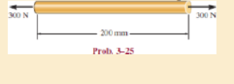
The acrylic plastic rod is 200 mm long and 15 mm in diameter. If an axial load of 300 N is applied to it, determine the change in its length and the change in its diameter. Ep = 2.70 GPa, vp = 0.4
Expert Solution & Answer
Want to see the full answer?
Check out a sample textbook solution
Students have asked these similar questions
The acrylic plastic rod is 200 mm long and 15 mm in diameter. If an axial load of 300 N is applied to it, determine the change in its length and the change in its diameter. Ep = 2.70 GPa, np = 0.4.
The acrylic plastic rod is 200 mm long and
15 mm in diameter. If an axial load of 300
N is applied to it, what is the change in its
diameter? E, = 2.70 GPa, v, = 0.5.
300 N
300 N
200 mm
Select one:
a. -4.72 µm
O b. -6.29 µm
C. -3.77 µm
d. 3.77 µm
е. 4.72 um
O f. None
A uniform edge load of 500 lb>in. and 350 lb>in. is applied to the polystyrene specimen. If the specimen is originally square and has dimensions of a = 2 in., b = 2 in., and a thickness of t = 0.25 in., determine its new dimensions a , b , and t after the load is applied. Ep = 597(103) psi andnp = 0.25.
Chapter 3 Solutions
Mechanics of Materials (10th Edition)
Ch. 3.4 - Define a homogeneous material.Ch. 3.4 - Indicate the points on the stress-strain diagram...Ch. 3.4 - Define the modulus of elasticity E.Ch. 3.4 - At room temperature, mild steel is a ductile...Ch. 3.4 - Engineering stress and strain are calculated using...Ch. 3.4 - As the temperature increases the modulus of...Ch. 3.4 - A 100-mm-long rod has a diameter of 15 mm. If an...Ch. 3.4 - A bar has a length of 8 in. and cross-sectional...Ch. 3.4 - A 10-mm-diameter rod has a modulus of elasticity...Ch. 3.4 - The material for the 50-mm-long specimen has the...
Ch. 3.4 - The material for the 50-mm-long specimen has the...Ch. 3.4 - If the elongation of wire BC is 0.2 mm after the...Ch. 3.4 - A tension test was performed on a steel specimen...Ch. 3.4 - Data taken from a stress-strain test for a ceramic...Ch. 3.4 - Data taken from a stress-strain test for a ceramic...Ch. 3.4 - The stress-strain diagram for a steel alloy having...Ch. 3.4 - The stress-strain diagram for a steel alloy having...Ch. 3.4 - The stress-strain diagram for a steel alloy having...Ch. 3.4 - The rigid beam is supported by a pin at C and an...Ch. 3.4 - The rigid beam is supported by a pin at C and an...Ch. 3.4 - Acetal plastic has a stress-strain diagram as...Ch. 3.4 - The stress-strain diagram for an aluminum alloy...Ch. 3.4 - The stress-strain diagram for an aluminum alloy...Ch. 3.4 - The stress-strain diagram for an aluminum alloy...Ch. 3.4 - A bar having a length of 5 in. and cross-sectional...Ch. 3.4 - The rigid pipe is supported by a pin at A and an...Ch. 3.4 - The rigid pipe is supported by a pin at A and an...Ch. 3.4 - Direct tension indicators are sometimes used...Ch. 3.4 - The rigid beam is supported by a pin at C and an...Ch. 3.4 - The rigid beam is supported by a pin at C and an...Ch. 3.4 - The stress-strain diagram for a bone is shown, and...Ch. 3.4 - The stress-strain diagram for a bone is shown and...Ch. 3.4 - The two bars are made of a material that has the...Ch. 3.4 - The two bars are made of a material that has the...Ch. 3.4 - The pole is supported by a pin at C and an A-36...Ch. 3.4 - The bar DA is rigid and is originally held in the...Ch. 3.7 - A 100-mm-long rod has a diameter of 15 mm. If an...Ch. 3.7 - A solid circular rod that is 600 mm long and 20 mm...Ch. 3.7 - A 20-mm-wide block is firmly bonded to rigid...Ch. 3.7 - A 20-mm-wide block is bonded to rigid plates at...Ch. 3.7 - The acrylic plastic rod is 200 mm long and 15 mm...Ch. 3.7 - The plug has a diameter of 30 mm and fits within a...Ch. 3.7 - The elastic portion of the stress-strain diagram...Ch. 3.7 - The elastic portion of the stress-strain diagram...Ch. 3.7 - The brake pads for a bicycle tire are made of...Ch. 3.7 - The lap joint is connected together using a 1.25...Ch. 3.7 - The lap joint is connected together using a 1.25...Ch. 3.7 - The rubber block is subjected to an elongation of...Ch. 3.7 - The shear stress-strain diagram for an alloy is...Ch. 3.7 - A shear spring is made from two blocks of rubber,...Ch. 3 - The elastic portion of the tension stress-strain...Ch. 3 - The elastic portion of the tension stress-strain...Ch. 3 - The rigid beam rests in the horizontal position on...Ch. 3 - The wires each have a diameter of 12 in., length...Ch. 3 - The wires each have a diameter of 12 in., length...Ch. 3 - diameter steel bolts. If the clamping force in...Ch. 3 - The stress-strain diagram for polyethylene, which...Ch. 3 - The pipe with two rigid caps attached to its ends...Ch. 3 - The 8-mm-diameter bolt is made of an aluminum...Ch. 3 - An acetal polymer block is fixed to the rigid...
Additional Engineering Textbook Solutions
Find more solutions based on key concepts
The magnitude of vector force F (F) and its direction θ.
Engineering Mechanics: Statics & Dynamics (14th Edition)
The spring has a stiffness k = 200 N/m and is unstretched when the 25-kg block is at A. Determine the accelerat...
Engineering Mechanics: Dynamics (14th Edition)
What parts are included in the vehicle chassis?
Automotive Technology: Principles, Diagnosis, and Service (5th Edition)
Comprehension Check 7-1
Express the following values using an appropriate Sl prefix such that there are only on...
Thinking Like an Engineer: An Active Learning Approach (3rd Edition)
Determine the force in members BC, CF, and FE and state if the members are in tension or compression. Prob. F5-...
Statics and Mechanics of Materials (5th Edition)
What parts are included in the vehicle chassis?
Automotive Technology: Principles, Diagnosis, And Service (6th Edition) (halderman Automotive Series)
Knowledge Booster


Learn more about
Need a deep-dive on the concept behind this application? Look no further. Learn more about this topic, mechanical-engineering and related others by exploring similar questions and additional content below.Similar questions
- A plastic rod is 200mm long and 15mm in diameter. If a tensile load of 300N is applied to it, determine the change in its length and the change in its diameter. Assume Modulus of elasticity (E) = 2.70 GPa, and poisson's ratio (v) = 0.4. indicate free body diagramarrow_forwardIn the graft, the 6-meter-high arm is manufactured using the l profile given below. It is fixed to both ends of the arm with a built-in support. If the yield strength of the material is σy=400 MPa Elasticity modulus E=2*105 MPa If the safety factor used in the design is 2.5, the arm in question is What is the highest axial load it can safely carry?arrow_forwardQuestion 1 A tensile load of 40 kN is acting on a rod of diameter 40 mm and of length 4 m. A bore of diameter 20 mm is made centrally on the rod. To what length the rod should be bored so that the total extension will increase 30% under the same tensile load. Take E = 2 x 10$ N/mm2.arrow_forward
- Need asap A round brass rod 30 mm in diameter and 200 mm long is subjected to a compressive force of 100 kN. If μ = 0.33 and E = 105 GPa. Determine the change in diameter. In mm. Thanksarrow_forwardA bar made of a space age polymer has the stress-strain curve shown below. If the bar has a length of 2 ft and a cross section area of 0.925 in², and an axial load of 2 kip is applied, what is its elongation? The equation of the stress-strain curve is: o = o (psi) The elongation,8 = in. 96000.28 + ε (in/inarrow_forwardA copper bar consists from three sections: sections 1 is of 25 mm diameter and 60 mm long, section 2 is of 15 mm diameter and 50 mm long and section 3 is 20 mm square and 40 mm long. The bar is subjected to an axial tensile load which induces a stress of 20 MN/m2 on the smallest cross section. Determine the total Increase in the length of the bar when the load is applied. For copper E=100 GN/m2.arrow_forward
- A uniform edge load of w1 = 530 lb/in. and w2 = 320 lb/in. is applied to the polystyrene specimen. Ep = 597(103)psi and νp = 0.25. 1) Part A: If the specimen is originally square and has dimensions of a = 1 in ., b = 2 in., and a thickness of t = 0.35 in. , determine its new dimension a′ after the load is applied. 2) Part B: Determine its new dimension b′ after the load is applied. 3) Part C: Determine its new dimension t′ after the load is applied.arrow_forward2. A circular steel bar with with a diameter of 3 in and length of 2 m is subjected to an tensile force of 80 kN. Determine the change in length and the change in its cross section if the material behaves elastically. Let y be the longitudinal axis and Modulus of Elasticity be 200 GPa. Assume v=0.32arrow_forward3. The aluminum block has the rectangular cross-section and is subjected to an axial compressive force of 8 kips. The 1.5-in side changed its length to 1.50014 inches. Use E = 10 x 10³ ksi. Calculate the new length of the 2-inch side. Answer: Lnew = 2.00019 in 1.5 in 2 in. 8 kip- 8 kip 3 in. 4. A solid cylinder of diameter D is subjected to an axial load P. Show that its change in diameter is 8D = 4Pv/лDE.arrow_forward
- The copper bar is subjected to a uniform loading shown in Fig. 10–24. Ifit has a length a = 300 mm, width b = 50 mm, and thickness t = 20 mmbefore the load is applied, determine its new length, width, and thicknessafter application of the load. Take Ecu = 120 GPa, ncu = 0.34.arrow_forwardThe pole is supported by a pin at B and A-36 steel guy wire AC. If the wire has a diameter of 0.2. Modulus of Elasticity of Steel = 200GPA or 29x103 ksi Poisson's ratio of steel=0.321 a. Determine how much the wire stretches when the horizontal force acts on the pole. 3 ft 30 D 2.5 kip 4 ft B b. Determine the change in the wire's radius c. At what angle is the principal stresses on pole BC? Use Mohr's Circle. d. What is the principal stress in pol BC? Use Mohr's Circle e. Draw the stresses on a unit element acting on 35-degree clockwise direction of pole BC. Use Mohr's Circle. f. What are the principal stresses in point D? Use Mohr's Circle. (answer in ksi) g. At what angle is the principal stresses acting on point D? Use Mohr 's Circle. h. Draw the stresses on a unit element acting on 35degree-clockwise direction of point D. Use Mohr's Circle. (answer in ksi)arrow_forwardThe timber member has a cross-sectional area of 1750 mm? and its modulus of elasticity is 12 GPa. Compute the change in the total length of the member after the loads shown in Figure 7 are applied. 25KH 20 KN 3akN 1.5m 3 marrow_forward
arrow_back_ios
SEE MORE QUESTIONS
arrow_forward_ios
Recommended textbooks for you
 Elements Of ElectromagneticsMechanical EngineeringISBN:9780190698614Author:Sadiku, Matthew N. O.Publisher:Oxford University Press
 Mechanics of Materials (10th Edition)Mechanical EngineeringISBN:9780134319650Author:Russell C. HibbelerPublisher:PEARSON
 Thermodynamics: An Engineering ApproachMechanical EngineeringISBN:9781259822674Author:Yunus A. Cengel Dr., Michael A. BolesPublisher:McGraw-Hill Education
 Control Systems EngineeringMechanical EngineeringISBN:9781118170519Author:Norman S. NisePublisher:WILEY
 Mechanics of Materials (MindTap Course List)Mechanical EngineeringISBN:9781337093347Author:Barry J. Goodno, James M. GerePublisher:Cengage Learning
 Engineering Mechanics: StaticsMechanical EngineeringISBN:9781118807330Author:James L. Meriam, L. G. Kraige, J. N. BoltonPublisher:WILEY
Elements Of Electromagnetics
Mechanical Engineering
ISBN:9780190698614
Author:Sadiku, Matthew N. O.
Publisher:Oxford University Press
Mechanics of Materials (10th Edition)
Mechanical Engineering
ISBN:9780134319650
Author:Russell C. Hibbeler
Publisher:PEARSON
Thermodynamics: An Engineering Approach
Mechanical Engineering
ISBN:9781259822674
Author:Yunus A. Cengel Dr., Michael A. Boles
Publisher:McGraw-Hill Education
Control Systems Engineering
Mechanical Engineering
ISBN:9781118170519
Author:Norman S. Nise
Publisher:WILEY
Mechanics of Materials (MindTap Course List)
Mechanical Engineering
ISBN:9781337093347
Author:Barry J. Goodno, James M. Gere
Publisher:Cengage Learning
Engineering Mechanics: Statics
Mechanical Engineering
ISBN:9781118807330
Author:James L. Meriam, L. G. Kraige, J. N. Bolton
Publisher:WILEY
EVERYTHING on Axial Loading Normal Stress in 10 MINUTES - Mechanics of Materials; Author: Less Boring Lectures;https://www.youtube.com/watch?v=jQ-fNqZWrNg;License: Standard YouTube License, CC-BY