
Mechanics of Materials (10th Edition)
10th Edition
ISBN: 9780134319650
Author: Russell C. Hibbeler
Publisher: PEARSON
expand_more
expand_more
format_list_bulleted
Videos
Textbook Question
thumb_up100%
Chapter 3.4, Problem 3.17P
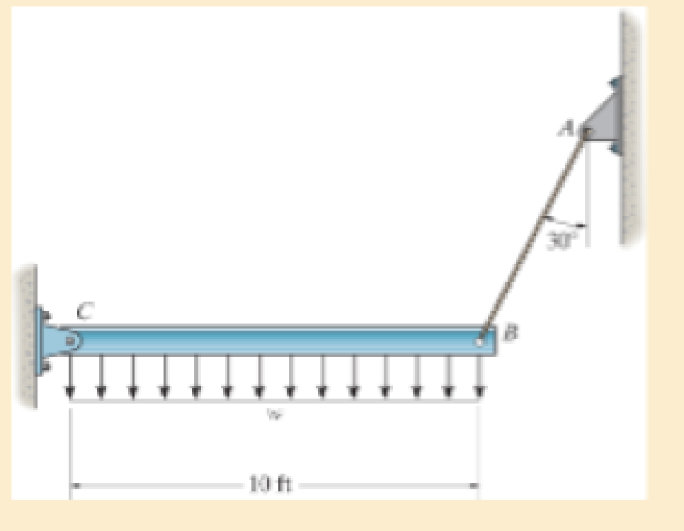
The rigid beam is supported by a pin at C and an A992 steel guy wire AB of length 6 ft. If the wire has a diameter of 0.2 in., determine how much it stretches when a distributed load of w = 200 lb/ft acts on the beam. The wire remains elastic.
Expert Solution & Answer
Want to see the full answer?
Check out a sample textbook solution
Students have asked these similar questions
The rigid beam is supported by a pin at C and an A992 steel guy wire AB of length 6 ft. If the wire has a diameter of 0.2 in., determine how much it stretches when a distributed load of w = 200 lb>ft acts on the beam. The wire remains elastic.
The strut is supported by a pin at C and an A-36 steel guy wire AB. If the wire has a diameter of 1,2 m , determine how much it stretches when the distributed load acts on the strut.
The pole is supported by a pin at B and A-36 steel guy wire AC. If the wire has a diameter of
0.2. Modulus of Elasticity of Steel = 200GPA or 29x103 ksi Poisson's ratio of steel=0.321
a. Determine how much the wire stretches when the horizontal force acts on the pole.
3 ft
30
D 2.5 kip
4 ft
B
b. Determine the change in the wire's radius
c. At what angle is the principal stresses on pole BC? Use Mohr's Circle.
d. What is the principal stress in pol BC? Use Mohr's Circle
e. Draw the stresses on a unit element acting on 35-degree clockwise direction of pole BC. Use
Mohr's Circle.
f. What are the principal stresses in point D? Use Mohr's Circle. (answer in ksi)
g. At what angle is the principal stresses acting on point D? Use Mohr 's Circle.
h. Draw the stresses on a unit element acting on 35degree-clockwise direction of point D. Use Mohr's
Circle. (answer in ksi)
Chapter 3 Solutions
Mechanics of Materials (10th Edition)
Ch. 3.4 - Define a homogeneous material.Ch. 3.4 - Indicate the points on the stress-strain diagram...Ch. 3.4 - Define the modulus of elasticity E.Ch. 3.4 - At room temperature, mild steel is a ductile...Ch. 3.4 - Engineering stress and strain are calculated using...Ch. 3.4 - As the temperature increases the modulus of...Ch. 3.4 - A 100-mm-long rod has a diameter of 15 mm. If an...Ch. 3.4 - A bar has a length of 8 in. and cross-sectional...Ch. 3.4 - A 10-mm-diameter rod has a modulus of elasticity...Ch. 3.4 - The material for the 50-mm-long specimen has the...
Ch. 3.4 - The material for the 50-mm-long specimen has the...Ch. 3.4 - If the elongation of wire BC is 0.2 mm after the...Ch. 3.4 - A tension test was performed on a steel specimen...Ch. 3.4 - Data taken from a stress-strain test for a ceramic...Ch. 3.4 - Data taken from a stress-strain test for a ceramic...Ch. 3.4 - The stress-strain diagram for a steel alloy having...Ch. 3.4 - The stress-strain diagram for a steel alloy having...Ch. 3.4 - The stress-strain diagram for a steel alloy having...Ch. 3.4 - The rigid beam is supported by a pin at C and an...Ch. 3.4 - The rigid beam is supported by a pin at C and an...Ch. 3.4 - Acetal plastic has a stress-strain diagram as...Ch. 3.4 - The stress-strain diagram for an aluminum alloy...Ch. 3.4 - The stress-strain diagram for an aluminum alloy...Ch. 3.4 - The stress-strain diagram for an aluminum alloy...Ch. 3.4 - A bar having a length of 5 in. and cross-sectional...Ch. 3.4 - The rigid pipe is supported by a pin at A and an...Ch. 3.4 - The rigid pipe is supported by a pin at A and an...Ch. 3.4 - Direct tension indicators are sometimes used...Ch. 3.4 - The rigid beam is supported by a pin at C and an...Ch. 3.4 - The rigid beam is supported by a pin at C and an...Ch. 3.4 - The stress-strain diagram for a bone is shown, and...Ch. 3.4 - The stress-strain diagram for a bone is shown and...Ch. 3.4 - The two bars are made of a material that has the...Ch. 3.4 - The two bars are made of a material that has the...Ch. 3.4 - The pole is supported by a pin at C and an A-36...Ch. 3.4 - The bar DA is rigid and is originally held in the...Ch. 3.7 - A 100-mm-long rod has a diameter of 15 mm. If an...Ch. 3.7 - A solid circular rod that is 600 mm long and 20 mm...Ch. 3.7 - A 20-mm-wide block is firmly bonded to rigid...Ch. 3.7 - A 20-mm-wide block is bonded to rigid plates at...Ch. 3.7 - The acrylic plastic rod is 200 mm long and 15 mm...Ch. 3.7 - The plug has a diameter of 30 mm and fits within a...Ch. 3.7 - The elastic portion of the stress-strain diagram...Ch. 3.7 - The elastic portion of the stress-strain diagram...Ch. 3.7 - The brake pads for a bicycle tire are made of...Ch. 3.7 - The lap joint is connected together using a 1.25...Ch. 3.7 - The lap joint is connected together using a 1.25...Ch. 3.7 - The rubber block is subjected to an elongation of...Ch. 3.7 - The shear stress-strain diagram for an alloy is...Ch. 3.7 - A shear spring is made from two blocks of rubber,...Ch. 3 - The elastic portion of the tension stress-strain...Ch. 3 - The elastic portion of the tension stress-strain...Ch. 3 - The rigid beam rests in the horizontal position on...Ch. 3 - The wires each have a diameter of 12 in., length...Ch. 3 - The wires each have a diameter of 12 in., length...Ch. 3 - diameter steel bolts. If the clamping force in...Ch. 3 - The stress-strain diagram for polyethylene, which...Ch. 3 - The pipe with two rigid caps attached to its ends...Ch. 3 - The 8-mm-diameter bolt is made of an aluminum...Ch. 3 - An acetal polymer block is fixed to the rigid...
Knowledge Booster


Learn more about
Need a deep-dive on the concept behind this application? Look no further. Learn more about this topic, mechanical-engineering and related others by exploring similar questions and additional content below.Similar questions
- The strut is supported by a pin at C and an A-36 steel (Young’s Modulus is 200 GPa) guy wire AB. If the wire has a diameter of 5 mm, determine how much it stretches when the distributed load acts on the strut. W0=11Kn/marrow_forwardA cable with supports at the same elevation has a span of 600 ft and a sag of 60 ft. The cable supports a uni- formly distributed load of 750 lb/ft along the horizontal. Determine The length of the cable.arrow_forwardThe rigid beam is supported by a pin at C and an A-36 steel guy wire AB. 30 10 ft Part A If the wire has a diameter of 0.5 in., determine how much it stretches when a distributed load of 190 lb/ft acts on the beam. The material remains elastic. Express your answer to three significant figures and include appropriate units. µA ? SAB = 0.02668 inarrow_forward
- The rigid beam is supported by a pin at C and an A-36 steel guy wire AB. If the wire has a diameter of 0.2 in., determine the distributed load w if the end B is displaced 0.75 in. downward.arrow_forwardQ14 Find the load .if the load distance 3m and effort distance 10m and effort=300N Effort Pivot Loadarrow_forwardProblem #2: The strut is by a pin at C and a A-36 steel guy wire AB (E = 200 GPa). If the wire has a diameter 5 mm, determine how much it stretches when the distributed load acts on the strut. A 60° 3.4 kN/m В 2.7 m Solve only by using this Donot nse equation &= AS'-AS AEarrow_forward
- The pole is supported by a pin at C and an A-36 steel guy wire AB. If the wire has a diameter of 0.2 in., determine how much it stretches when a horizontal force of 2.5 kip acts on the pole.arrow_forwardThe horizontal beam is assumed to be rigid while supporting the distributed load. Determine the angle of inclination of the beam after the load is applied. Each support consists of a wooden post with a diameter of 120 mm and an original length (unloaded) of 1.40 m- Consider E = 12 GPaarrow_forwardA steel column is of length 8m and diameter 600 mm with both ends hinged.Determine the crippling load by Euler’s formula. Take 5 E = 2.1x10 N/mm2arrow_forward
- All the pins are in double shear, and they each have a diameter of 14 mm. The average shear stress in each pin CANNOT exceed 70 MPa. What is the max magnitude of P that the beam can supportarrow_forwardA leaf spring 75 cm long is required to carry a central load of 8 kN. If the central deflection is not to exceed 2 cm and bending stress no greater than 200 MPa, determine the thickness, width and number of plates. Also compute the radius to which plates should be curved. As- sume width of plate to be 12 times its thickness and E = 200 GPa.arrow_forwardThe simply supported beam is built up from three boards by nailing them together as A, В shown. Determine the L1 L2 maximum allowable bf spacing s of the nails to support that load, if each nail can resist a tf tw shear force of V kN. hw tf P=17KN V=2kN L1=3.1m L2=2.5m bf=120mm tf=20mm hw=270mm tw=15mmarrow_forward
arrow_back_ios
SEE MORE QUESTIONS
arrow_forward_ios
Recommended textbooks for you
 Elements Of ElectromagneticsMechanical EngineeringISBN:9780190698614Author:Sadiku, Matthew N. O.Publisher:Oxford University Press
 Mechanics of Materials (10th Edition)Mechanical EngineeringISBN:9780134319650Author:Russell C. HibbelerPublisher:PEARSON
 Thermodynamics: An Engineering ApproachMechanical EngineeringISBN:9781259822674Author:Yunus A. Cengel Dr., Michael A. BolesPublisher:McGraw-Hill Education
 Control Systems EngineeringMechanical EngineeringISBN:9781118170519Author:Norman S. NisePublisher:WILEY
 Mechanics of Materials (MindTap Course List)Mechanical EngineeringISBN:9781337093347Author:Barry J. Goodno, James M. GerePublisher:Cengage Learning
 Engineering Mechanics: StaticsMechanical EngineeringISBN:9781118807330Author:James L. Meriam, L. G. Kraige, J. N. BoltonPublisher:WILEY
Elements Of Electromagnetics
Mechanical Engineering
ISBN:9780190698614
Author:Sadiku, Matthew N. O.
Publisher:Oxford University Press
Mechanics of Materials (10th Edition)
Mechanical Engineering
ISBN:9780134319650
Author:Russell C. Hibbeler
Publisher:PEARSON
Thermodynamics: An Engineering Approach
Mechanical Engineering
ISBN:9781259822674
Author:Yunus A. Cengel Dr., Michael A. Boles
Publisher:McGraw-Hill Education
Control Systems Engineering
Mechanical Engineering
ISBN:9781118170519
Author:Norman S. Nise
Publisher:WILEY
Mechanics of Materials (MindTap Course List)
Mechanical Engineering
ISBN:9781337093347
Author:Barry J. Goodno, James M. Gere
Publisher:Cengage Learning
Engineering Mechanics: Statics
Mechanical Engineering
ISBN:9781118807330
Author:James L. Meriam, L. G. Kraige, J. N. Bolton
Publisher:WILEY
Mechanics of Materials Lecture: Beam Design; Author: UWMC Engineering;https://www.youtube.com/watch?v=-wVs5pvQPm4;License: Standard Youtube License