
(a)
The section for loads given loads using load and resistance factor design (LRFD) method.
Answer to Problem 3.8.1P
The section for loads given loads using load and resistance factor design (LRFD) method is
Explanation of Solution
Given data:
Length of the connection is
Spacing of truss in the roof system is
Snow load is
Weight of roofing is
Section for the purlins is
Weight of the truss is
Calculation:
Calculate the snow load.
Calculate the load due to purlins.
Calculate the weight of the truss.
Calculate the slant height of the roof.
Calculate the weight of the roof.
Write the expression to calculate the total dead load.
Here, total dead load is
Substitute
Calculate the factored load using following load combination.
Here, factored load is
Substitute
Write the expression to calculate the exterior joint load.
Here, load on the exterior joint is
Substitute
Consider the free body diagram of the truss shown below.
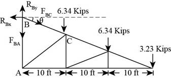
Figure-(1)
Write the expression to calculate the moment about point
Substitute
Solve further.
Consider joint
Write the expression for summation of forces acting in the horizontal direction.
Here, summation of all horizontal forces is
Substitute
Write the expression to calculate the required area.
Here, gross area is
Substitute
Write the expression to calculate the required area.
Here, effective area is
Substitute
Calculate the effective length of the truss.
Calculate the radius of gyration.
Substitute
Use section
Write the expression to calculate reduction factor.
Here, reduction factor is
Substitute
Write the expression to calculate the effective area for the section.
Substitute
Conclusion:
Since the gross area, net area and radius of gyration for this greater than the calculated value,
(b)
The section for loads given loads using allowable strength design (ASD) method.
Answer to Problem 3.8.1P
The section for loads given loads using allowable strength design (ASD) method is
Explanation of Solution
Given data:
Length of the connection is
Spacing of truss in the roof system is
Snow load is
Weight of roofing is
Section for the purlins is
Weight of the truss is
Calculation:
Calculate the ultimate load using the following load combination.
Here, ultimate load is
Substitute
Write the expression to calculate the exterior joint load.
Here, load on the exterior joint is
Substitute
Consider the free body of the truss as shown below.
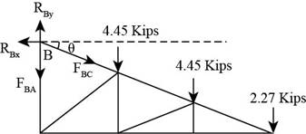
Figure-(2)
Write the expression to calculate the moment about point
Substitute
Solve further.
Consider joint
Write the expression for summation of forces acting in the horizontal direction.
Here, summation of all horizontal forces is
Substitute
Write the expression to calculate the required area.
Here, gross area is
Substitute
Write the expression to calculate the required area.
Here, effective area is
Substitute
Calculate the effective length of the truss.
Calculate the radius of gyration.
Substitute
Use section
Write the expression to calculate reduction factor.
Here, reduction factor is
Substitute
Write the expression to calculate the effective area for the section.
Substitute
Conclusion:
Since the gross area, net area and radius of gyration for this greater than the calculated value,
Want to see more full solutions like this?
Chapter 3 Solutions
Steel Design (Activate Learning with these NEW titles from Engineering!)

- 2. See connection figure below. The rivets is 7/8 in. in diameter. According to the rivert supplier, the allowable stresses for the material are t = 15 ksi and on = 32 ksi. What is the allowable load of the connection? L4 x 3-1/2 W18 x 86 W24 x 117 Girder Beamarrow_forwardA 15" x 3/8" bar of A572 Gr. 50 steel is used as a tension member. It is connected to a gusset plate with 7/8-in diameter bolts as shown in the figure. Use s = 2.0 and g = 3.0.a) Determine the design tensile strength of the section based on yielding of the gross area.b) Determine the critical net area of the connection shown.arrow_forwardTopic:Welded Connection - Civil Engineering -Steel Design *Use latest NSCP/NSCP 2015 formula to solve this problem *Please use hand written to solve this problem A tension member consists of a double angle section with long legs back to back. The angles are attached to a 9.5 mm thick gusset plate. Fu = 400 MPa Fy = 248 MPa for angular section. Fw = 480 MPa for 8 mm fillet weld. Reduction factor U = 0.80 Prop. of One Angle L 125m x 75m x 12.7 m A= 2419 mm2 y=44.45 mm Questions: a) Compute the design strength capacity of one angle. b) Compute the base metal shear strength (gusset plate) per unit length. c) Compute the length L1 and L2.arrow_forward
- Determine the maximum service load P that can be resisted safely by the welded connection shown. Use ASD. E80 10 150 300 200arrow_forwardThe truss below is pin connected at A and E, and is acted on by the forces shown. E A D B Identify all of the ZERO-FORCE MEMBERS by checking the boxes below (if there are none, leave all boxes unchecked): BF AF BC BH CD EG -GH AB CH DG DH DE -FHarrow_forward
 Steel Design (Activate Learning with these NEW ti...Civil EngineeringISBN:9781337094740Author:Segui, William T.Publisher:Cengage Learning