
(a)
The maximum factored load using Load and Resistance Factor Design (LRFD).
Answer to Problem 3.5.4P
The maximum factored load using LRFD is
Explanation of Solution
Given:
The following figure shows the A36 steel connection with
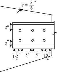
Figure-(1)
Concept Used:
Write the expression for the factored strength in yielding.
Write the expression for the factored strength in rupture.
Here, the factored yielding strength of the material is
Write the expression for block shear.
Write the expression for the upper limit of block shear.
Here, the upper limit is
Write the expression for the design block shear strength.
Here the design block shear strength, the minimum of Equation (III) and (IV), is
The maximum factored load is the minimum of Equation (I), (II), and (V).
Write the expression for the nominal strength in yielding for the tension member.
Here, the yield strength in yielding is
Write the expression for the nominal strength in rupture for the tension member.
Here, the yield strength in rupture is
Write the expression for the effective area.
Here, the area reduction factor is
Write the expression for the area reduction factor.
Here the distance from the centroid of the connected area
Write the expression for the net area of the tension member.
Here, the thickness of the tension member is
Write the expression for the diameter of the holes.
Here the diameter of the bolts is
Calculation:
Calculate the nominal shear strength of the tension member in yielding.
Substitute
Calculate the diameter of the holes.
Substitute
Calculate the net area of the tension member.
Substitute
Calculate the length of the connection.
Calculate the area reduction factor.
Substitute
Calculate the effective area of the member.
Substitute
Calculate the nominal shear strength of the tension member in rupture.
Substitute
Calculate the net area along the shear surface of the tension member.
Calculate the net area along the tension surface of the tension member.
Calculate the gross area along the shear surface in the gusset plate.
Calculate the net area along the shear surface of the gusset plate.
Substitute further.
Calculate the net area along the tension surface of the gusset plate.
Calculate the shear strength for the tension member.
Substitute
Calculate the upper limit.
Substitute
The value of the shear is larger than the upper limit. Hence, it is not feasible.
Adopt the shear strength of the tension member to be
Calculate the shear strength for the gusset plate.
Substitute
Calculate the upper limit
Substitute
The value of the shear is larger than the upper limit. Hence, it is not feasible.
Adopt the shear strength of the gusset plate to be
Compare the shear strength of the tension member and that of the gusset plate.
Thus the block shear strength is
Calculate the design block shear strength of the connection.
Calculate the factored yielding strength.
Substitute
Calculate the factored rupture strength.
Substitute
Calculate the factored strength of block shear.
Substitute
Conclusion:
Thus, the maximum factored load is
(b)
The allowable block shear strength of the connection.
Answer to Problem 3.5.4P
The allowable block shear strength of the connection is
Explanation of Solution
Concept used:
Write the expression for the factored design block shear strength.
Here the safety factor is
Calculation:
Calculate the allowable block shear strength of the connection.
Calculate the allowable yielding strength.
Substitute
Calculate the allowable rupture strength.
Substitute
Calculate the factored strength of block shear.
Substitute
Conclusion:
Thus, the maximum allowable block shear strength of the connection is
Want to see more full solutions like this?
Chapter 3 Solutions
Steel Design (Activate Learning with these NEW titles from Engineering!)

- A bearing type connection is shown in Figure 3.19. The diameter of A 325 bolts is 22 mm and the A572 Grade 50 plate material has a width of 150 mm and thickness of 16 mm. Assume diameter hole to be 24 mm. Bolt threads are excluded from the shear plane. Allowable stress of A 325 bolts: Fv = 207 MPa Fp = 1.5 Fu (to prevent excessive hole deformation) Allowable stresses of A572 Grade 50 plate material: Fy = 345 MPa Fu = 450 MPa a. Compute the tensile capacity due to the failure of the plates. b. Compute the tensile capacity due to the failure of the bolts.arrow_forwarda. Under a heavy vibrating loads it is possible that a fully tensioned bolt may come loose. As a steel design engineer suggest two possible solutions that you would recommend to your clientsarrow_forwardConsidering the following steel connection. The plates in Pink are 9mm steel plates. The middle plate (Yellow) is 18mm thick. The width of the plate is 100mm. The maximum allowable tension stresses on any of the plates is 100Mpa in Gross Area Yielding and 150 Mpa for Net Area or Tension Rupture. The bolts used are 8mm in diameter, the holes are 10mm in diameter, no need to add 1.6mm. The bolts allow a maximum of 280 Mpa of shear. Determine the maximum allowable "P" of the connection in kN.arrow_forward
- The given angle bar L125x75x12 with Ag = 2,269 sq.mm. is connected to a gusset plate using 20 mm diameter bolts as shown in the figure. Using A36 steel with Fy = 248 MPa and Fu = 400 MPa, determine the following: 2. Determine the nominal tensile strength of the 12 mm thick, A36 angle bar shown based on: a. Gross yielding b. Tensile rupture Bolts used for the connection are 20 mm in diameter. O O O O O O O Effective net area of the tension member if the shear lag factor is 0.80. Select the correct response: 1,516.1 1,354.4 1,431.2 1,221.6arrow_forward7) The connection shows a PL10X200 loaded in tension and welded to a 10mm gusset plate. Calculate the following, assuming A36 steel is used. • The design strength in gross yielding • The allowable strength in tensile rupture 350mm PL 10 X 200arrow_forwardSITUATION 14: A PL 300 x 20 mm is to be connected to two plates of the same material with half the thickness by 25 mm Ø rivets as shown in the figure. The rivet holes have a diameter 2 mm larger than the rivet diameter. The plate is A36 steel with Fy= 250 MPa, allowable tensile stress of 0.60Fy and allowable bearing stress of 1.35Fy. The rivets are A502, Grade 2, hotdriven rivets with allowable shear stress of 150 MPa. 25 mm Ø rivets + + PL 300x20 P/2 P P/2 PL 300x10 43. Which of the following most nearly gives the max. load in kN that can be applied to the connection without exceeding the allowable shear stress in the rivets? a. 675 KN b. 490 KN c. 598 KN d. 790.5 kN 44. Which of the following most nearly gives the max. load in kN that can be applied to the connection without exceeding the allowable bearing stress between the plates and the rivets? a. 490 KN b. 675 KN c. 598 KN d. 790.5 kN 45. Which of the following most nearly gives the max. load in kN that can be applied to the…arrow_forward
- Topic:Welded Connection - Civil Engineering -Steel Design *Use latest NSCP/NSCP 2015 formula to solve this problem *Please use hand written to solve this problem A channel is used as a tension member with the web of the channel welded to a 9.5 mm thick gusset plate as shown in the figure. The tension member is subjected to the following axial loads. Use LRFD Service dead load = 200 kN Wind load = 276 kN Service live load = 260 kN For channel: Fy = 345 MPa For gusset plate: Fy = 248 MPa Fu = 400 MPa Size of E 70 electrodes = 4 mm Ultimate tensile strength of E 70 electrodes = 480; Fw = 0.6(480) Questions : a) Determine the design factored tensile force. b) Determine the length of longitudinal welds "L". c) Determine the block shear strength of the gusset plate.arrow_forwardTopic:Bolted Steel Connection - Civil Engineering -Steel Design *Use latest NSCP/NSCP 2015 formula to solve this problem *Please use hand written to solve this problem A channel shown is attached to a 12 mm gusset plate with 9-22 mm diameter A 325 bolts as shown. Use LRFD. Fnv = 300 MPa Fu = 400 MPa Fy = 248 MPa Ag = 3354 mm2 Question: Determine the capacity of the channel based on the bearing strength of the connection.arrow_forwardTopic:Welded Connection - Civil Engineering -Steel Design *Use latest NSCP/NSCP 2015 formula to solve this problem *Please use hand written to solve this problem A 150 mm x 90 mm x 12 mm angular section is welded to a gusset plate as shown. Area of the angle is 2736 sq.mm, allowable shear Fv is 150MPa, Allowable tensile stress Ft = 0.6Fy with Fy = 250 MPa. Questions: a) Design force P b) Total required length of weld using 12 mm fillet weld c) Value of “b”arrow_forward
- The butt connection shows 8-22 mm diameter bolts spaced as shown below. P- 50 100 50 50 100 50 16 mm +HHHH 40 80 40 12 mm Steel strength and stresses are: Yield strength, Fy = 248 MPa Ultimate strength, Fu = 400 MPa Allowable tensile stress on the gross area = 148 MPa Allowable tensile stress on the net area = 200 MPa Allowable shear stress on the net area = 120 MPa Allowable bolt shear stress, Fv = 120 MPa Based on the gross area of the plate. Based on the net area of the plate. Based on block shear strength. Bolt hole diameter = 25 mm Calculate the allowable tensile load, P, under the following conditions:arrow_forwardTopic:Bolted Steel Connection - Civil Engineering *Use latest NSCP/NSCP 2015 formula to solve this problem The butt connection shows 8-22 mm dia. A325 bolts spaced as follows: S1 = 40 mm S3 = 50 mm t1 = 16 mm S2 = 80 mm S4 = 100 mm t2 = 12 mm Steel strength and stresses are: Fy = 248 MPa Fu = 400 MPa Allowable tensile stress on the gross area = 148 MPa Allowable tensile stress on the net area = 200 MPa Allowable shear stress on the net area = 120 MPa Allowable bolt shear stress, Fv = 120 MPa Bolt Hole diameter = 25 mm Questions: Calculate the allowable tensile load T, under the following conditions. a) Based on the gross area of the plate b) Based on the net area of the plate c) Based on block shear strengtharrow_forwardThe plate shown is 8 in wide and 1/2 in thick. The bolts are 7/8 in. The smallest net area (An) of this bolted plate is equal to:arrow_forward
 Steel Design (Activate Learning with these NEW ti...Civil EngineeringISBN:9781337094740Author:Segui, William T.Publisher:Cengage Learning
 Architectural Drafting and Design (MindTap Course...Civil EngineeringISBN:9781285165738Author:Alan Jefferis, David A. Madsen, David P. MadsenPublisher:Cengage Learning